Chapter 7
Wave Optics
Maharashtra HSC · 10 subtopics · textbook pages 158–185
Formula SheetEvery formula this chapter can be examined on, in one table.
Light as a Wave
| Formula | Symbols, units and conditions |
|---|---|
| |
| |
| |
| |
|
Huygens' Theory
| Formula | Symbols, units and conditions |
|---|---|
|
Reflection of Light at a Plane Surface
| Formula | Symbols, units and conditions |
|---|---|
| |
|
Refraction of Light at a Plane Boundary
| Formula | Symbols, units and conditions |
|---|---|
| |
| |
| |
| |
|
Polarization
| Formula | Symbols, units and conditions |
|---|---|
| |
| |
| |
| |
| |
|
Interference
| Formula | Symbols, units and conditions |
|---|---|
| |
| |
| |
| |
| |
| |
| |
| |
| |
|
Optical Path and Fringe Shift
| Formula | Symbols, units and conditions |
|---|---|
| |
| |
|
Methods of Obtaining Coherent Sources
| Formula | Symbols, units and conditions |
|---|---|
| |
| |
|
Diffraction at a Single Slit
| Formula | Symbols, units and conditions |
|---|---|
| |
| |
| |
| |
| |
|
Resolving Power
| Formula | Symbols, units and conditions |
|---|---|
| |
| |
| |
| |
| |
|
Useful conversions
- m; nm m Å; m.
- Visible light: nm (violet) to nm (red).
- rad; arcsec of a degree.
- m/s.
Short NotesThe chapter subtopic by subtopic, in the textbook's own order.10 subtopics
- 1Introduction
- 2Nature of Light
- 3Light as a Wave
- 4Huygens' Theory3 board questions
- 5Reflection of Light at a Plane Surface1 board question
- 6Refraction of Light at a Plane Boundary Between Two Media16 board questions
- 7Polarization6 board questions
- 8Interference23 board questions
- 9Diffraction of Light6 board questions
- 10Resolving Power5 board questions
The whole chapter in brief
7.1 Introduction — what is already assumed
- Ray optics (geometrical optics) treats light as travelling in straight lines and explains shadows, mirrors, lenses and prisms.
- Laws of reflection: (i) incident ray, reflected ray and normal are coplanar; (ii) .
- Laws of refraction: (i) incident ray, refracted ray and normal are coplanar; (ii) .
- Ray optics works because the wavelength of light is far smaller than everyday obstacles and apertures.
7.2 Nature of Light
- Corpuscular theory (Descartes 1636, developed by Newton): light is a stream of hard, elastic, massless corpuscles travelling in straight lines. Explained rectilinear propagation, reflection (elastic collision) and image formation.
- Its fatal flaw: it required the speed of light in a denser medium to be GREATER than in a rarer medium, which contradicts experiment. It also could not explain interference, diffraction or polarization.
- Wave theory (Huygens, 1668): light is a wave in a hypothetical all-pervading medium called ether. It explained reflection, refraction, image formation and the new nineteenth-century phenomena, and correctly required .
- Ether was never detected (Michelson and Morley); Einstein's special theory of relativity (1905), built on the constancy of the speed of light, made it unnecessary.
- Maxwell showed light is an electromagnetic wave; Hertz verified radio waves travel at the speed of light.
- Dual nature: light behaves as a wave in interference, diffraction and polarization, and as particles (photons) in phenomena such as the photoelectric effect.
| Corpuscular theory | Wave theory |
|---|---|
| Light is a stream of particles | Light is a wave |
| Predicts (wrong) | Predicts (correct) |
| Cannot explain interference, diffraction, polarization | Explains all three |
| Colour = size of corpuscle | Colour = wavelength |
7.3 Light as a Wave
- Light is a transverse electromagnetic wave: mutually perpendicular oscillating electric and magnetic fields, both perpendicular to the direction of propagation.
- It needs no material medium and travels through vacuum at m/s.
- ; depends on the permeability and permittivity of the medium and on the wavelength of the light.
- EM spectrum in increasing order of wavelength: gamma rays, X-rays, ultraviolet, visible, infrared, microwaves, radio waves.
- Visible range – nm: violet shortest, red longest. White light is a mixture of all these wavelengths.
- Because depends on , the angle of refraction differs for different colours at the same angle of incidence (except at normal incidence) — this is dispersion, and it explains the spectrum and the rainbow.
7.4 Huygens' Theory
- Primary sources emit light of their own — because of high temperature (Sun, stars, flames), because current is passed through them (tube light, TV), or by chemical/nuclear reaction (firecrackers, reactors).
- Secondary sources do not produce light; they reflect or scatter light received from elsewhere (moon, planets, people, plants). Most are extended sources.
- Wavefront: the locus of all points of the medium that are in the same phase at a given instant, i.e. all points reached simultaneously by waves starting from the source.
- Rays are always perpendicular to the wavefront and give the direction of propagation. The wavefront moves with the speed of the wave.
- Shapes: spherical for a point source; cylindrical for a linear source; plane for a small portion of a wavefront very far from the source (parallel rays).
- Huygens' principle: every point on a wavefront acts as a secondary source emitting secondary wavelets in all directions with the speed of light in the medium; the new wavefront is the forward envelope of these wavelets. Backward wavelets are ineffective.
- Limitation: the theory is empirical — there is no reason within it why backward wavelets should be ineffective. It was accepted only because it explained the observations.
7.5 Reflection at a Plane Surface
- Huygens construction: plane wavefront hits mirror at while is still at ; in the time that takes to reach , the wavelet from grows to radius in the SAME medium.
- The reflected wavefront is the envelope. Triangles and are congruent (right angle, equal side, common hypotenuse), giving , hence .
- The incident ray, reflected ray and normal lie in one plane — the second law.
- Size of the image equals the size of the object (equal distances between corresponding reflected rays).
- Lateral inversion: the right side of the object appears as the left side of the image. It happens in reflection but NOT in refraction at a plane surface.
7.6 Refraction at a Plane Boundary
- Same construction, but the wavelet from spreads in the SECOND medium: while .
- , , so — Snell's law.
- Going rarer to denser, , so , hence : the speed of light in a rarer medium is greater than in a denser medium. This is exactly what corpuscular theory got backwards.
- Frequency is unchanged; speed and wavelength change: , and in general .
- In the denser medium the successive wavefronts are more closely spaced, because they travel a shorter distance in the same time.
- No lateral inversion in refraction; but at oblique incidence the image looks bent (broken) at the surface. At normal incidence there is no bending.
7.7 Polarization
- Unpolarized light: electric field vectors in all possible directions in the plane perpendicular to propagation (drawn as double-headed arrows in all directions).
- Plane polarized light: the electric field is restricted to one direction (drawn as double-headed arrows in one direction only).
- Polarization is the restriction of the vibrations of a light wave to a single plane perpendicular to the direction of propagation.
- Polarizer: a material transmitting only waves whose electric field lies along its polarizing axis. A polaroid is a synthetic plastic sheet used as a polarizer.
- Plane of vibration contains the electric field vector; the plane of polarization is perpendicular to it.
- Only TRANSVERSE waves can be polarized. Longitudinal waves (sound) cannot, because their particles already vibrate along one direction — the direction of propagation — so there is nothing left to restrict. Polarization is therefore the phenomenon that proves light is a transverse wave.
- Unpolarized light loses half its intensity through the first polarizer: (average of is ).
- Malus' law: , being the angle between the axes of the two polarizers. parallel setting (maximum), cross setting (zero).
- Brewster's law: . At the polarizing angle the reflected light is completely plane polarized (electric field perpendicular to the plane of incidence) and the refracted light is only partially polarized; the reflected and refracted rays are then perpendicular, .
- Polarization by reflection works only for non-metallic surfaces; polaroid sunglasses use it to cut glare.
- Polarization by scattering: sunlight scattered by air molecules is partially polarized; light scattered through exactly is plane polarized. Preferential scattering of blue light is why the sky is blue.
7.8 Interference
- Interference is the modification of the intensity of light — larger at some places, smaller at others — produced by the superposition of two or more light waves.
- Constructive interference: crest on crest, resultant amplitude , intensity . Destructive: crest on trough, resultant amplitude and intensity zero (for equal amplitudes).
- Coherent sources emit waves of the same frequency with a constant phase difference independent of time. Two independent primary sources are never coherent, which is why no interference is seen in everyday life; both secondary sources must be derived from one primary source.
- Young's double slit experiment: a plane wavefront falls on two narrow slits , (2–4 mm apart) which act as coherent secondary sources; fringes are seen on a screen at m.
| Quantity | Result |
|---|---|
| Path difference at | |
| Bright fringe | , |
| Dark fringe | , |
| Fringe width | , same for bright and dark |
| Intensity |
- Central fringe is bright and is the ZEROTH bright fringe, not the first.
- Unequal amplitudes: maxima , minima — minima are no longer dark and the contrast falls.
- Conditions for a good, steady pattern: (1) coherent sources; (2) monochromatic sources; (3) equal amplitudes; (4) ; (5) narrow slits; (6) same state of polarization if polarized light is used.
- Methods of obtaining coherent sources: Lloyd's mirror (direct light plus light reflected at grazing incidence, appearing to come from a virtual source) and Fresnel biprism (vertex angle nearly ; the two halves form virtual images and of one slit).
- Optical path actual path: the distance in vacuum producing the same phase change. It is always larger than the actual path.
- A plate of thickness , refractive index , in front of one slit adds to that path, so the whole pattern shifts towards that slit by ; the fringe width is unchanged.
- Thin films (soap bubbles, oil on water): light partially reflected from the top surface and light reflected from the bottom surface interfere. The path difference depends on the angle of viewing, on the thickness, and (through ) on the wavelength — so different colours are seen at different angles. Reflection at the denser boundary adds an extra phase difference of , i.e. an extra path difference of .
7.9 Diffraction of Light
- Diffraction is the bending of light at the edge of an obstacle or slit and its spreading into the region of the geometrical shadow.
- Light does not really bend: secondary sources on the wavefront at the edges send wavelets into the shadow region. Diffraction is the interference of many waves from the same wavefront.
- It is noticeable only when the size of the obstacle or slit is comparable with the wavelength. Sound diffracts obviously because its wavelength is large.
- Fraunhofer diffraction: source, obstacle and screen all effectively at infinity, so the incident wavefront is plane. Lenses are used to make the wavefront plane and to focus the pattern. Fresnel diffraction: distances are small, incident wavefront cylindrical or spherical, no lens required.
- Single slit, width : minima at ; secondary maxima (taken as midway between minima) at .
- between consecutive bands; the central maximum is wide, twice as wide as any other bright band, and much the brightest.
- The first minimum uses (not ) between the extreme rays, because that gives between every pair of points separated by across the slit — so all pairs cancel.
- Double slit diffraction: narrow interference fringes of varying brightness, with the single slit diffraction pattern as their envelope.
| Interference | Diffraction |
|---|---|
| Superposition of waves from two different wavefronts | Superposition of many waves from different parts of the same wavefront |
| All bright fringes of equal intensity | Intensity falls with the order of the bright band |
| Minimum intensity may be zero | Minimum intensity is not zero |
| All fringes, including the central one, are of the same width | Central maximum is twice as wide as the others |
| Waves from two coherent sources travel in straight lines | Waves are bent at the corners, away from the straight-line path |
| Resolving power of an instrument does not depend on it | Resolving power of an instrument depends on it |
| ( = slit separation) | ( = slit width) |
| Bright: ; Dark: | Bright: ; Dark: |
7.10 Resolving Power
- Resolving power is the ability of an optical instrument to distinguish two physically separated objects as two distinct objects.
- The minimum visual angle between two objects that can just be resolved is the limit of resolution; resolving power is its reciprocal.
- Rayleigh's criterion: two objects are just resolved when the first minimum of the diffraction pattern of one coincides with the central maximum of the other. Unresolved if the separation of the central maxima ; just resolved if ; well resolved if , where is the central-maximum-to-first-minimum distance. The dip in the resultant envelope is not noticeable, just noticeable and clearly noticeable respectively.
- Point objects give an Airy disc surrounded by concentric rings; the criterion becomes "first dark ring of one falls at the centre of the other".
- Two linear objects: and least separation .
- Microscope, non-luminous objects: , with .
- Microscope, self-luminous point objects: , .
- Resolving power of a microscope depends on the numerical aperture of the objective and on the wavelength. Increase it by using an oil-immersion objective (larger ) and light of shorter wavelength.
- Telescope: , . It depends on the aperture of the objective and on the wavelength — a larger objective resolves better.
- Because large lenses are hard to make and handle, front-coated parabolic mirrors, and now segmented hexagonal mirrors, are used as telescope objectives.
- Radio telescopes need enormous apertures because radio wavelengths are metres long; arrays are used instead — the GMRT at Narayangaon near Pune has 30 dishes of 45 m diameter spread over 25 km.
Traps that cost marks
- Frequency does not change from medium to medium. Wavelength and speed do.
- In INTERFERENCE the bright fringes obey ; in single slit DIFFRACTION it is the dark fringes that obey . Students routinely swap these.
- The central fringe in Young's experiment is the zeroth bright fringe, so the dark fringe is at , not .
- A thin plate in front of one slit SHIFTS the pattern; it does not change the fringe width. A plate covering both slits changes nothing.
- Unpolarized light entering the first polarizer gives regardless of orientation; Malus' law applies only from the second polarizer onwards.
- In Malus' law is the angle between the two polarizing AXES. If one axis is at to the vertical and the other is horizontal, , not .
- Brewster angle uses , the critical angle uses . Do not mix them.
- If a question gives the angle a ray makes with the SURFACE, the angle of incidence is minus that. A ray at to a water surface has .
- Convert Å to metres ( Å m) before substituting; most lost marks in this chapter are unit slips.
- gives radian. Convert to arcsec only if the question asks.
- The width of the central diffraction maximum is — remember the factor 2.
Solved Numerical ExamplesWorked numericals to attempt first, each with a hint before the full solution.Coming soon
These are being added chapter by chapter. They are solved numericals from the prescribed book and the reference guides — not previous board questions, which live under Practice — so that you can work through the method before meeting it in a real paper.
Important DerivationsEvery derive / obtain / prove question in this chapter. 2 have come up in two or more papers.4
- 1Laws of reflection of light using Huygens' principle RepeatsDerive the laws of reflection of light using Huygens' principle.
Asked in: July 2022 (Q.18, 3 marks); February 2023 (Q.15, 3 marks)
Show the derivationHide the derivation
Reflection of light on a plane surface:Step 1A plane wavefront AB is advancing obliquely towards plane reflecting surface XY with velocity 'v'. and are incident rays.Step 2When 'A' reaches XY at , then ray at 'B' reaches point 'P' and it has to cover distance to reach the reflecting surface XY.Step 3Let 't' be the time required to cover distance . During this time interval, secondary wavelets are emitted from and will spread over a hemisphere of radius , in the same medium. Distance covered by secondary wavelets to reach from to R in time t is same as the distance covered by primary waves to reach from P to . Thus .Step 4All other rays between and will reach XY after and before . Hence, they will also emit secondary wavelets of decreasing radii.Step 5The surface touching all such hemispheres is which is reflected wavefront, bounded by reflected rays and .Step 6Draw and .Thus, angle of incidence is and angle of reflection is .andStep 7In and(Reflected waves travel equal distance in same medium in equal time).….(common side)Step 8Also, from the figure, it is clear that incident ray, reflected ray and normal lie in the same plane.Step 9This explains reflection of light from plane reflecting surface on the basis of Huygens' principle.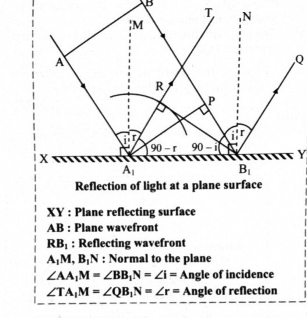
- 2Fringe width of interference bands (double slit) RepeatsUsing the geometry of the double slit experiment, derive the expression for the fringe width of interference bands. (Also asked using the analytical method.)
Asked in: July 2016; July 2019; February 2024 (Q.28, 4 marks); February 2026 (Q.31, 4 marks)
Show the derivationHide the derivation
Step 1Let and be the two coherent monochromatic sources which are separated by short distance d. They emit light waves of wavelength λ.Step 2Let D = horizontal distance between screen and source.Step 3Draw andOP = perpendicular bisector of slit.Since , the path difference between waves reaching P from and is zero, therefore there is a bright point at P.Step 4Consider a point Q on the screen which is at a distance y from the central point P on the screen. Light waves from and reach at Q simultaneously by covering path and , where they superimpose.Derivation:In ,In ,Subtract equation (1) from (2),If y << D and d << D then,Equation (3) becomes,Equation (4) gives the path difference of two interfering light waves.Point Q will be bright if,where n = 0, 1, 2,….Equation (5) represents distance of n bright fringe from central bright fringe.Point Q will be dark point if,where n = 1, 2, 3,……Equation (6) represents distance of n dark fringe from central maximum.Fringe width:The distance between any two successive dark or any two successive bright fringes is equal. This is called the fringe width and is given by,Fringe widthThus, both dark and bright fringes are equidistant and have equal widths.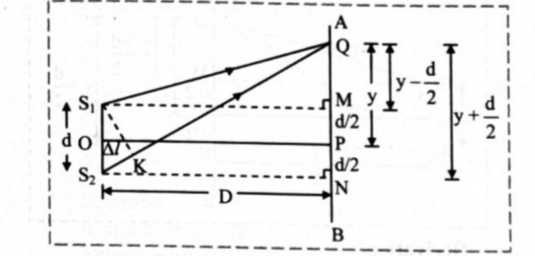
- 3Brewster's angleDerive the formula for Brewster's angle.
Asked in: July 2024 (Q.31(i), 4 marks)
Show the derivationHide the derivation
The phenomenon of restriction of the vibration of light waves in a particular plane perpendicular to direction of wave motion is called polarization of light.StatementThe tangent of the polarizing angle is equal to the refractive index of the refracting medium at which partial reflection takes place.According to Brewster's law,where, and are refractive indices of two media.Explanation of Brewster law:Step 1When light is incident at an angle on a boundary between two transparent media having refractive indices and , part of it gets refracted and the rest gets reflected.Step 2Consider unpolarized light incident from rarer medium of refractive index on such a boundary that is perpendicular to the plane of the paper, as shown below,Step 3For a particular angle of incidence (shown in the figure), the reflected wave is completely plane polarized with its electric field perpendicular to the plane of the paper while the refracted wave is partially polarized. This particular angle of incidence is called the Brewster's angle .Step 4For this angle of incidence, the refracted and reflected rays are perpendicular to each other.For angle of refraction ,From laws of refraction,,This is the expression for Brewster's angle.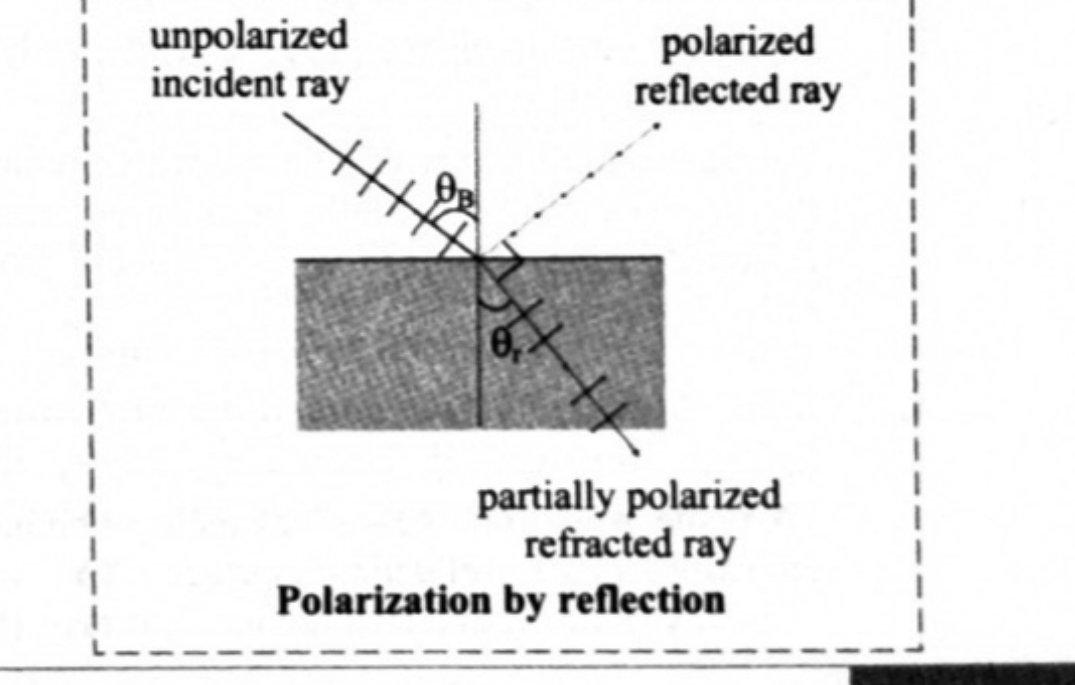
- 4Using Huygens' principle, prove that light travels faster in a rarer medium than in a denser mediumOn the basis of Huygens' wave theory of light, prove that the velocity of light in a rarer medium is greater than the velocity of light in a denser medium.
Asked in: March 2013
Show the derivationHide the derivation
Explanation:Step 1Let XY be the plane refracting surface separating two media air and glass of refractive indices and respectively.Step 2A plane wavefront AB is advancing obliquely towards XY from air. It is bounded by rays and which are incident rays.Step 3When 'A' reaches '', then 'B' will be at 'P'. It still has to cover distance to reach XY.Step 4According to Huygens' principle, secondary wavelets will originate from and will spread over a hemisphere in glass.Step 5All the rays between and will reach XY and spread over the hemispheres of decreasing radii in glass. The surface of tangency of all such hemispheres is . This gives rise to refracted wavefront in glass.Step 6and are refracted rays.Step 7Let and be the velocities of light in air and glass respectively.Step 8At any instant of time 't', distance covered by incident wavefront from P toDistance covered by secondary wave from to .Proof of laws of refraction:Step 1From figure,andFrom equations (1) and (2),Step 2Similarly,We have,andFrom equations (3) and (4),Step 3In ,Step 4In ,Step 5Dividing equation (5) by (6),AlsoStep 6From the explanation, it is clear that incident rays , , refracted rays , and normal MN and lie on the same plane XY. Also, incident ray and refracted ray lie on opposite sides of normal MN. Hence, laws of refraction can be explained.vi. From figure,Step 7Since,Hence, velocity of light in rarer medium is greater than velocity in denser medium.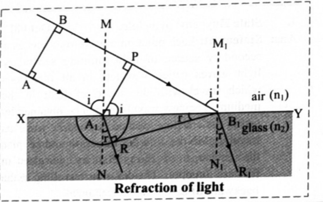
Finished revising this chapter? Practise Wave Optics →