Chapter 8
Electrostatics
Maharashtra HSC · 10 subtopics · textbook pages 186–213
Formula SheetEvery formula this chapter can be examined on, in one table.
Constants and conventions
- is the permittivity of free space; in numericals use .
- Permittivity of a medium , where is the dielectric constant (relative permittivity). For air or vacuum . Every field formula below is written for air — insert an extra in the denominator for a medium.
- Charge densities: linear in ; surface in .
- Electronic charge , so charge carried by electrons is .
- , , .
Gauss' law
| Formula | Symbols, units and conditions |
|---|---|
|
Application of Gauss' law
| Formula | Symbols, units and conditions |
|---|---|
| |
| |
| |
| |
| |
|
Electric potential and potential energy
| Formula | Symbols, units and conditions |
|---|---|
| |
| |
| |
| |
|
Potential due to a point charge, a dipole and a system of charges
| Formula | Symbols, units and conditions |
|---|---|
| |
| |
| |
| |
| |
|
Equipotential surfaces
| Formula | Symbols, units and conditions |
|---|---|
|
Electrostatic potential energy of point charges and of a dipole
| Formula | Symbols, units and conditions |
|---|---|
| |
| |
| |
| |
| |
| — | |
|
Dielectrics and electric polarisation
| Formula | Symbols, units and conditions |
|---|---|
| |
| |
|
Capacitors and capacitance, combinations
| Formula | Symbols, units and conditions |
|---|---|
| |
| |
| |
|
Parallel plate capacitor, with and without a dielectric
| Formula | Symbols, units and conditions |
|---|---|
| |
| |
| |
| |
| |
| |
| |
| |
| |
|
Displacement current
| Formula | Symbols, units and conditions |
|---|---|
|
Energy stored in a capacitor
| Formula | Symbols, units and conditions |
|---|---|
| |
| |
| |
|
Short NotesThe chapter subtopic by subtopic, in the textbook's own order.10 subtopics
- 1Introduction
- 2Application of Gauss' law7 board questions
- 3Electric Potential and Potential Energy
- 4Equipotential Surfaces1 board question
- 5Electrostatic Potential Energy of Two Point Charges and of a Dipole in an Electrostatic Field1 board question
- 6Dielectrics and Electric Polarisation3 board questions
- 7Capacitors and Capacitance, Combination of Capacitors in Series and Parallel10 board questions
- 8Capacitance of a Parallel Plate Capacitor Without and With Dielectric Medium Between the Plates3 board questions
- 9Energy Stored in a Capacitor5 board questions
- 10Van de Graaff Generator2 board questions
The whole chapter in brief
8.1 Introduction
- Gauss' law: the flux of the net electric field through a closed surface equals the net charge enclosed divided by , i.e. .
- It is a tool for finding whenever the charge distribution has enough symmetry — spherical, cylindrical or planar.
- Standard steps the board expects: identify the charge density (linear, surface, volume); choose a Gaussian surface matching the symmetry; write the flux from Gauss' law; write the flux again by direct calculation using the geometry; equate the two and solve for .
8.2 Application of Gauss' law
| Charge distribution | Gaussian surface | Result |
|---|---|---|
| Uniformly charged spherical shell, point outside | Concentric sphere of radius | |
| Same shell, point on the surface | Sphere of radius | |
| Same shell, point inside | Sphere of radius | |
| Infinitely long straight charged wire or cylinder | Coaxial cylinder of length , radius | |
| Charged infinite plane sheet | Cylinder of area , length , axis normal to the sheet |
- A uniformly charged sphere is equivalent to a point charge at its centre for all external points.
- For the wire, the flat end caps contribute nothing (, ); all the flux passes through the curved surface, area .
- For the sheet, the curved surface contributes nothing; both end caps contribute each, so .
- Distance dependence — the classic marks-loser: sphere , wire , sheet independent of .
- In a medium of dielectric constant every one of these is divided by : e.g. outside a charged cylinder.
- Just outside any charged conductor, , normal to the surface, and the outward mechanical force per unit area is .
8.3 Electric potential and potential energy
- Electrostatic potential energy is the work done against electrostatic forces to bring a system of charges to a given configuration from infinite separation.
- Because the Coulomb force is conservative, and hence the work done depends only on the end points, never on the path.
- For a fixed charge and a test charge moved from to : . Taking at gives .
- Potential ; potential difference , the work per unit charge. Potential is a scalar.
- Potential at a point A is the work done in bringing unit positive charge from infinity to A.
- Relation with field: , so — the field is the negative gradient of the potential.
- Zero of potential is arbitrary but must be fixed: infinity for point charges and localised distributions, earth for circuits.
- Units: joule for energy; is the kinetic energy an electron gains across a potential difference of 1 volt.
- Trap: at a point does not force there (midpoint of two equal like charges), and does not force (equatorial plane of a dipole).
8.4 Potential due to a point charge, a dipole and a system of charges
- Point charge: , spherically symmetric, independent of the direction of , and zero at infinity. A positive charge gives positive potential, a negative charge negative potential.
- Short dipole, general point at distance and angle to the axis: , obtained by binomial expansion keeping terms of first order in .
- Axial point (): , the maximum. Equatorial point (): , the minimum, so the equatorial plane is a zero-potential equipotential plane and no work is done moving a charge anywhere in it.
- System of charges: — an algebraic sum with signs, replaced by an integral for a continuous distribution.
- Standard comparison: for a single point charge , but ; for a short dipole .
8.5 Equipotential surfaces
- An equipotential surface is one on which the potential is the same at every point.
- No work is done in moving a test charge anywhere on an equipotential surface, since makes .
- is always normal to the equipotential surface. If it were not, it would have a component along the surface, and moving a charge against that component would need work — contradicting the definition.
- Equipotential surfaces never intersect: at an intersection there would be two directions of at one point, which is impossible.
- Standard shapes to describe: concentric spheres about an isolated point charge; coaxial cylinders about a line charge; equally spaced parallel planes perpendicular to the field for a uniform field; closed curves that are symmetric about the perpendicular bisector for a dipole (with the equatorial plane as the zero surface); the surfaces between two plane metallic sheets, or between a sheet and a charged sphere, following the electrodes.
- Like lines of force, they picture both the direction of the field (normal to them) and its magnitude (closer surfaces mean a stronger field).
8.6 Electrostatic potential energy of two point charges and of a dipole
- Definition: the total work done in assembling the system of charges by bringing them from infinity to their present positions.
- Two charges: — bringing the first charge in costs nothing, bringing the second costs (potential due to the first) .
- charges: ; for three charges there are three pairs, for four charges six pairs.
- Single charge in an external field: . Two charges in an external field: — students routinely forget the last, mutual, term.
- Dipole in a uniform field: it feels a torque of magnitude but zero net force, so it rotates without translating. Torque is maximum () when the dipole is perpendicular to the field, zero when it is parallel or antiparallel.
- Work done by the external torque in turning the dipole: ; this is stored as potential energy.
- Zero-level convention: choosing at gives ; choosing at gives . State the convention you use.
- Board exercise result worth remembering: for , , placed at equal spacings on a straight line, zero total potential energy requires .
- Flux check: for a Gaussian sphere, only the charge actually inside contributes, so a sphere of radius centred at the origin enclosing only has flux regardless of the charge sitting outside at .
8.7 Conductors and insulators, free and bound charges
| Conductor | Insulator (dielectric) |
|---|---|
| Has a large number of free charge carriers (loosely bound valence electrons) | Electrons are tightly bound to the nucleus; no free charges |
| Net electrostatic field in the interior is zero | Field inside can have non-zero values |
| Potential is constant within and on the surface | No such constraint |
| Interior carries no charge; charge resides on the surface | Charge can be distributed on the surface or in the interior |
| Field just outside is perpendicular to the surface at every point | — |
| Surface charge density may differ from point to point | — |
- Free charges: electrons in the outermost shells of a metal, which drift opposite to an applied field. Bound charges: nuclei and inner-shell electrons, immobile in their positions. In electrolytic conductors positive and negative ions carry the charge, with restricted movement.
- Electrostatic shielding: since inside a hollow conductor, a delicate instrument placed inside one is protected from external charges; thin metal foils make such shields. This is why a car is the safest place in a thunderstorm.
- Faraday cage: an enclosure that blocks external electric fields; MRI scan rooms are shielded so that external radio-frequency signals do not mix with the machine's signals.
8.8 Dielectrics and electric polarisation
- Dielectrics are insulators that can store electrical energy: placed in an external field, their positive and negative charges are displaced in opposite directions and the molecules develop a net dipole moment. This is polarisation. Examples: glass, wax, water, wood, mica, rubber, stone, plastic.
| Polar dielectric | Non-polar dielectric |
|---|---|
| Centre of mass of positive charges does not coincide with that of the negative charges | The two centres of mass coincide |
| Asymmetric molecular shape | Symmetric molecular shape |
| Permanent dipole moment of the order of | Zero dipole moment in the normal state |
| Examples: HCl, water, alcohol, | Examples: , , , , benzene, methane |
- Polarisation of a non-polar dielectric: the external field pulls the positive centre along the field and the negative centre against it, the molecule gets distorted, and displacement stops when the field force is balanced by the restoring force inside the molecule. Each molecule becomes a tiny dipole; the induced moments add to a net moment.
- Polarisation of a polar dielectric: the permanent moments are randomly oriented by thermal agitation, giving zero net moment; the applied field aligns them, so the slab acquires a net moment along the field. The degree of alignment is set by the competition between the applied field and the field of the induced dipoles.
- Both kinds develop a net dipole moment in a field. Alignment moves charges only over distances less than an atomic diameter, so no current flows.
- Polarisation is the dipole moment per unit volume; for linear isotropic dielectrics , where is the electric susceptibility ( for vacuum).
- Reduction of field: the aligned dipoles leave an apparent sheet of positive charge on one face and negative on the other. These induced surface charges set up a polarisation field opposing , so the net field inside is , smaller than the applied field.
- The induced moment disappears when the field is removed; it is what makes a charged comb attract uncharged bits of paper.
- Dielectric strength is the field at which a dielectric breaks down, gets ionised and begins to conduct. The dielectric constant of a conductor is infinite; that of air is 1.
8.9 Capacitors and capacitance, combinations
- A capacitor is a pair of conductors carrying equal and opposite charges, separated by a dielectric, used to store electrical energy (unlike a resistor, which only dissipates).
- Capacitance is the ability of a conductor to store charge. It depends on size, shape and separation of the conductors, and on the medium — not on or .
- SI unit farad: a capacitor has capacitance 1 farad if the potential difference across it rises by 1 volt when 1 coulomb of charge is given to it. Dimensions . Practical units are , nF and pF.
- Principle of a capacitor: bringing an earthed metal plate near a charged plate induces a negative charge on the near face of (which lowers the potential of ) and a positive charge on the far face (which flows to earth). The net potential of falls, so its capacitance rises.
| Series combination | Parallel combination |
|---|---|
| Same charge on every capacitor | Same potential difference across every capacitor |
| Potential differences add: | Charges add: |
| is smaller than the smallest capacitance | is larger than the largest capacitance |
| equal capacitors: | equal capacitors: |
| Used to divide a high voltage across several capacitors | Used to get a large capacitance at small potentials |
- In series, the capacitor of smallest capacitance carries the largest potential difference.
- For two capacitors in series the working form is .
- Mixed networks: reduce the innermost parallel groups first, then the series chain. For and in parallel, in series with : .
8.10 Parallel plate capacitor, with and without a dielectric
- The two plates each of area are held a distance apart; one is charged and the other earthed. In the outer regions the two plate fields cancel (); between them they add, giving , directed from the positive to the negative plate.
- With this gives — capacitance rises with plate area and falls with separation.
- Filling the gap completely with a dielectric of constant : , so .
- A slab of thickness : . A conducting slab () gives , always an increase, and independent of where the slab is placed.
- Standard result asked as an objective: a slab of thickness gives .
- Stacked slabs behave as capacitors in series; slabs side by side over parts of the area behave as capacitors in parallel.
| Battery still connected ( constant) | Battery disconnected ( constant) |
|---|---|
| becomes | becomes |
| unchanged | falls to |
| rises to | unchanged |
| unchanged | falls to |
| rises times | falls to |
- Read the reverse of the right-hand column for the standard question "the battery is disconnected and then the dielectric is removed": decreases, stays constant, and , and all increase times.
- For a charged and isolated capacitor whose plate separation is then increased: stays constant, decreases and increases.
- Displacement current (8.11): in the dielectric between the plates there are no free electrons, but the bound charges move, giving , equal to the conduction current in the leads. A displacement current exists at any point in space where varies with time.
8.12 Energy stored in a capacitor
- Charging a capacitor means transferring electrons from one plate to the other against the Coulomb forces of both plates, and the opposing force grows as the charge grows.
- Work to transfer a further is ; integrating from 0 to gives , stored as electrostatic energy in the field between the plates.
- Three equivalent forms: .
- Energy density in ; multiply by the volume of dielectric to get the energy contained in it.
- The battery does work but only is stored; the remaining half is lost as heat in the connecting wires and the battery. Hence energy stored : energy dissipated during charging is .
- Sharing charge between two capacitors always loses energy: , lost as heat and electromagnetic radiation.
8.13 Van de Graaff generator
- Purpose: to develop very high potentials, of the order of volt, whose large fields accelerate charged particles (electrons, protons, ions) to energies of the order of 10 MeV. Designed by Van de Graaff in 1931.
- Three principles: corona discharge (the action of sharp points); charge given to a hollow conductor moves entirely to its outer surface and spreads uniformly; continuously supplying charge to an insulated conductor raises its potential indefinitely.
- Labels for the diagram: , pulleys; BB insulating conveyor belt; A spray brush; C collector brush; D dome-shaped hollow metallic conductor; E evacuated accelerating tube; I electrode (ion source end); P high-voltage DC supply; S steel vessel filled with nitrogen at high pressure; M earthed metal plate.
- Working in one line: the motor drives the belt, brush A sprays positive charge on it, the belt carries the charge up to brush C which delivers it to the dome D, the charge spreads on the outer surface of D and its potential rises enormously, and positive ions introduced at the top of tube E are repelled by electrode I and accelerated down the tube to strike a target.
- Nitrogen at high pressure (with a little freon) inside the steel vessel prevents leakage of charge from the dome.
- Uses: disintegration of nuclei, production of radioactive isotopes, study of nuclear structure and of nuclear reactions, and accelerating electrons to sterilise food and process materials.
Solved Numerical ExamplesWorked numericals to attempt first, each with a hint before the full solution.Coming soon
These are being added chapter by chapter. They are solved numericals from the prescribed book and the reference guides — not previous board questions, which live under Practice — so that you can work through the method before meeting it in a real paper.
Important DerivationsEvery derive / obtain / prove question in this chapter. 1 have come up in two or more papers.6
- 1Equivalent capacitance of two capacitors in seriesObtain an expression for the equivalent capacitance of two capacitors and connected in series.
Asked in: February 2023 (Q.6, 2 marks)
Show the derivationHide the derivation
Step 1Diagram:Step 2Explanation:a. Capacitors are said to be connected in series if they are connected one after the other in the form of a chain.b. Let capacitors of capacitances C₁, C₂ be connected in series as shown in the figure.c. Let V₁, V₂ be the corresponding potential differences in the capacitors.d. Suppose a potential difference 'V' is applied across the combination. The left plate of capacitor C₁ has a charge +Q. An equal but opposite charge −Q is induced on the right plate of this capacitor. This charge −Q induces a charge +Q on the left plate of C₂.e. Thus, each capacitor receives a magnitude of charge Q. Hence, when the capacitors are connected in series, same current flows through them and all have the same charge +Q induced on the plate.Thus, potential difference induced across capacitors is given by,f. Total potential difference 'V' across the combination is given by,g. If these capacitors are replaced by a single capacitor of capacity , such that effective capacity remains same thenFrom equation (2) and (3),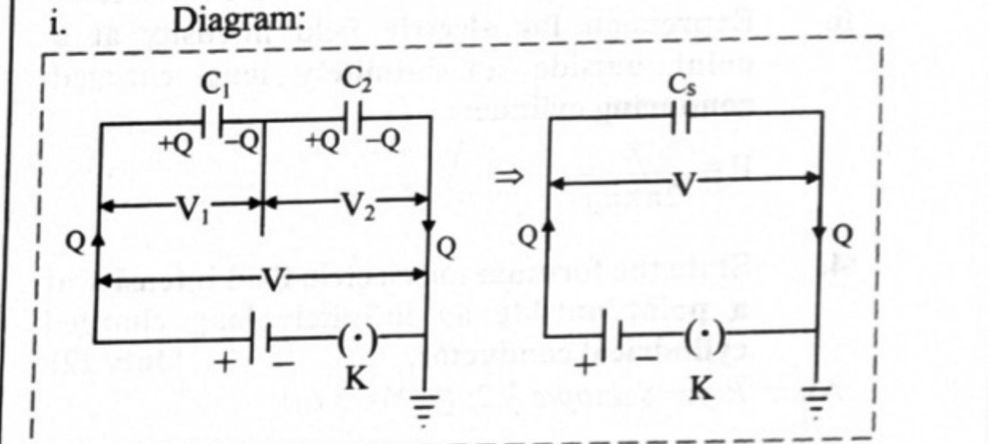
- 2Electric field intensity due to an infinitely long straight charged wireDerive an expression for electric field intensity due to an infinitely long straight charged wire.
Asked in: July 2023 (Q.4, 2 marks)
Show the derivationHide the derivation
Step 1Consider a uniformly charged wire of infinite length having a constant linear charge density λ (charge per unit length), kept in a medium of permittivity ε (ε = ε₀k).Step 2To find the electric field intensity at P, at a distance r from the axis of the charged wire, imagine a coaxial Gaussian cylinder of length and radius r (closed at each end by plane caps normal to the axis) passing through the point P as shown in the figure. Consider a very small area ds at the point P on the Gaussian surface.Step 3By Gauss' theorem, the net flux through a closed surface,where q is the total charge inside the closed surface.Step 4By symmetry, the magnitude of the electric field will be the same at all the points on the curved surface of the cylinder and will be directed radially outward. The angle between the direction of and the normal to the curved surface of the cylinder is zero. Similarly, the angle is (π/2) for the flat surface of the cylinder.i.e., (for curved surface) or (for flat surface)....(For flat surface)....(For curved surface)Flux dφ through the area ds,Total electric flux through the Gaussian surfaceStep 5From equations (1) and (2)Since ,The direction of the electric field E is directed outward if λ is positive and inward if λ is negative.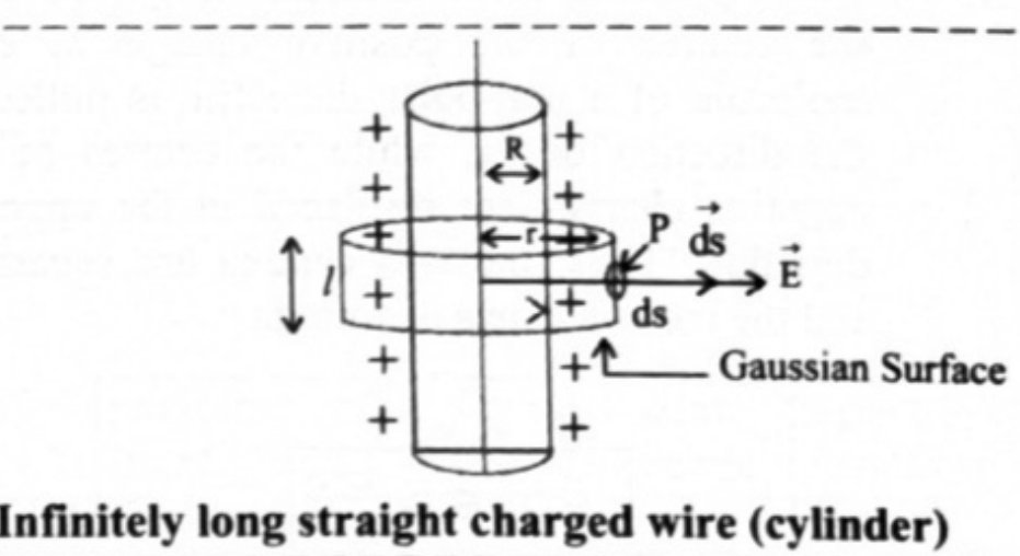
- 3Energy stored in a charged capacitorDerive an expression for energy stored in a charged capacitor.
Asked in: February 2024 (Q.31, 4 marks)
Show the derivationHide the derivation
Step 1Consider a capacitor of capacitance C being charged by a DC source of V volts as shown in figure below.Step 2During the process of charging, let q' be the charge on the capacitor and V be the potential difference between the plates. HenceStep 3A small amount of work is done if a small charge dq is further transferred between the plates.Step 4Total work done in transferring the chargeStep 5This work done is stored as electrical potential energy U of the capacitor. This work done can be expressed in different forms as follows.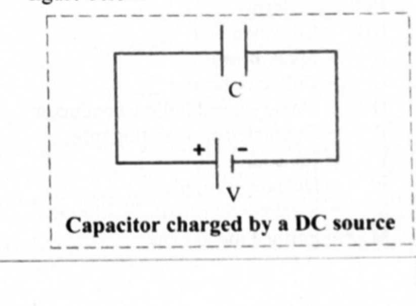
- 4Electric intensity outside a uniformly charged spherical shell RepeatsObtain an expression for the electric intensity at a point outside a uniformly charged spherical shell.
Asked in: October 2009; June 2025 (Q.18, 3 marks)
Show the derivationHide the derivation
Step 1Consider a sphere of radius R with its centre at O, charged to a uniform surface charge density σ placed in a dielectric medium of permittivity ε (ε = ε₀k). The total charge on the sphere, .Step 2To find the electric field intensity at a point P, at a distance r from the centre of the charged sphere, imagine a concentric Gaussian sphere of radius r passing through P as shown in the figure below. Let ds be a small area around the point P on the Gaussian surface.Step 3By Gauss' theorem, the net flux through a closed Gaussian surface,where q is the total charge inside the closed surface.Step 4Due to symmetry and spheres being concentric, the electric field at each point on the Gaussian surface has the same magnitude E and it is directed radially outward. Also, the angle between the direction of E and the normal to the surface of the sphere (ds) is zero i.e.Total electric flux through the Gaussian surfaceStep 5From equations (1) and (2),This is the expression for the electric intensity at the point P, outside the charged sphere.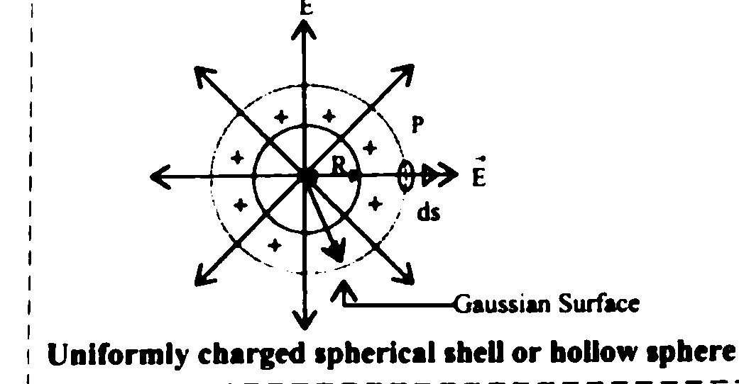
- 5Electric potential due to a point chargeDerive an expression for electric potential due to a point charge.
Asked in: February 2026 (Q.19, 3 marks)
Show the derivationHide the derivation
The question is a real board question. This working is ours — no source printed a derivation for it.
Diagram
Draw a point charge at a point and a point at a distance from it, with the line extended away to infinity. Mark an intermediate point at distance from on that line, and a small displacement from towards infinity. Show the test charge at and the outward force acting on it along produced.
Definition used
The electric potential at a point is the work done per unit charge in bringing a test charge from infinity to against the electric field:
Derivation
Let a test charge be at a distance from the source charge . By Coulomb's law the force on it is
To move the test charge through a small displacement **towards** the charge, the work done by the external agent against this repulsive force is
The negative sign appears because the displacement and the Coulomb force are oppositely directed. The total work in bringing the charge from infinity to the point at distance is
Dividing by the test charge,
Notes
- Potential is a scalar, so for several charges the potentials add
algebraically, with sign: .
- , whereas the field goes as .
- is positive around a positive charge and negative around a negative one,
and is taken as zero at infinity.
- 6Electric field intensity due to a uniformly charged thin plane sheetObtain an expression for the electric field intensity at a point outside a uniformly charged thin plane sheet.
Asked in: July 2017
Show the derivationHide the derivation
Step 1Consider a uniformly charged infinite plane sheet with uniform surface charge density (charge per unit area) σ kept in a medium of permittivity ε (ε = ε₀k).Step 2To find the electric field due to a charged infinite plane sheet at P at a distance r from the sheet, imagine a Gaussian surface around P in the form of a cylinder having cross sectional area A and length 2r with its axis perpendicular to the plane sheet. The plane sheet passes through the middle of the length of the cylinder such that the ends of the cylinder (called end caps P and P') are equidistant (at a distance r) from the plane sheet as shown in the figure below.Step 3By Gauss' theorem, the net flux through a closed surfacewhere q is the total charge inside the closed surface.Step 4By symmetry, electric field is perpendicular to the plane sheet and directed outwards, having the same magnitude at a given distance on either side of the sheet. The electric field is at right angles to the end caps and away from the plane. Its magnitude is the same at P and P'. The flux passing through the curved surface is zero as the electric field is tangential to this surface.The total flux through the closed Gaussian surface is given by,Step 5From equations (1) and (2),This is the required expression.Step 6Direction of electric field is outward if sheet is positively charged and inward if it is negatively charged.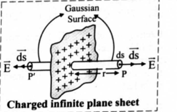
Finished revising this chapter? Practise Electrostatics →