8.9
Capacitors and Capacitance, Combination of Capacitors in Series and Parallel
Electrostatics · Maharashtra HSC
Theory
Why a capacitor is needed
- A resistor allows current to pass and dissipates heat, but cannot store electrical energy. A capacitor is the device developed to store it: a set of conductors carrying opposite charges, separated by a dielectric.
- Two conductors 1 and 2 carry charges and , with potential difference between them. The field in the region between them is proportional to , and the potential difference — the work done to carry a unit positive test charge from conductor 2 to conductor 1 against the field — is also proportional to . Hence and the ratio is a constant.
Capacitance
- The ability of a conductor to store electric charge is called the capacitance of the conductor:
- depends on the size, shape and separation of the system of two conductors, and on the medium between them — never on or separately.
- SI unit: farad (F), . A capacitor has a capacitance of one farad if the potential difference across it rises by 1 volt when 1 coulomb of charge is given to it.
- Dimensional formula . The farad is a very large unit in practice, so the submultiples are used: , , .
Principle of a capacitor
- Take a metal plate of area , give it a positive charge , and let its potential be ; its capacitance is .
- Bring another insulated metal plate near it. By induction a negative charge appears on the nearer face of and an equal positive charge on the farther face. The induced negative charge lowers the potential of , while the induced positive charge raises it. As the negative charge is closer it is more effective, so there is a net reduction in the potential of .
- If the outer surface of is earthed, the induced positive charge, being free, flows to earth; the induced negative charge stays, bound to the positive charge of . If is the potential due to this charge, the net potential difference is and
- So the capacitance of a plate is increased by placing an identical earthed plate near it. Such an arrangement is a capacitor. If the conductors are plane sheets it is a parallel plate capacitor; there are also spherical and cylindrical capacitors.
(a) Capacitors in series
Diagram and set-up
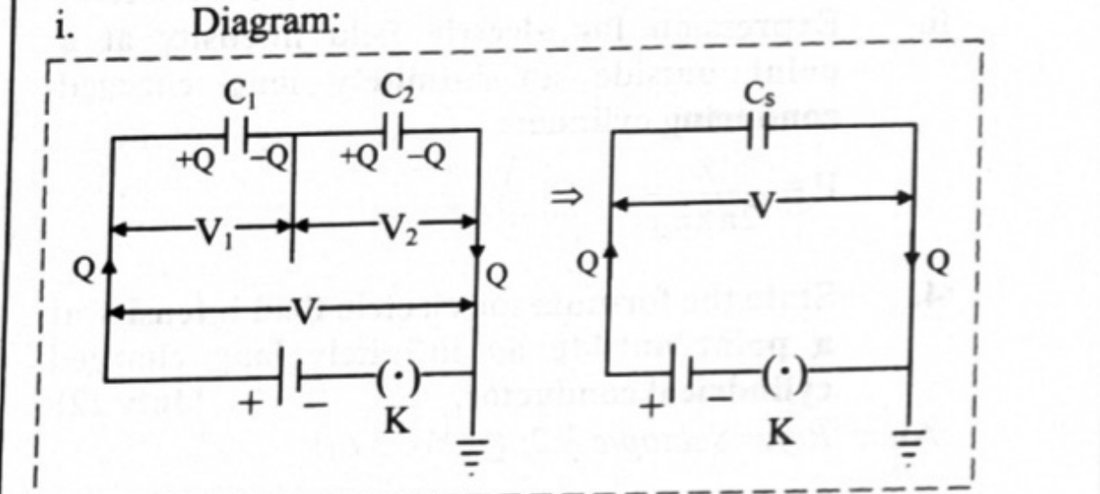
- Capacitors are in series when they are connected end to end in the form of a chain, so that the sum of the potential differences across them equals the applied potential difference . The second plate of the first capacitor is connected to the first plate of the second, and so on; the last plate is earthed.
- Draw and in a single line between the terminals, with the supply across the pair.
Derivation
- Suppose a potential difference is applied across the combination. The left plate of acquires a charge ; an equal and opposite charge is induced on its right plate; that in turn induces on the left plate of .
- Hence each capacitor carries the same magnitude of charge . The potential differences are
- The total potential difference is , so from (1)
- Replacing the combination by a single capacitor of capacitance with the same effect,
- From (2) and (3),
Generalisation
- For capacitors in series, the reciprocal of the equivalent capacitance equals the sum of the reciprocals of the individual capacitances:
- If all the capacitors are equal, , i.e. .
- A series combination is used when a high voltage is to be divided over several capacitors. The capacitor with the minimum capacitance has the maximum potential difference across its plates.
(b) Capacitors in parallel
Diagram and set-up
- The insulated plates of all the capacitors are connected to a common terminal A joined to the source of potential, and the other plates to another common terminal B which is earthed. Draw the capacitors as parallel branches between A and B.
Derivation
- In this combination all the capacitors have the same potential difference , but the plate charges , , are not necessarily the same: a charge supplied at A distributes itself according to the capacitances.
- The total charge is
- If is the equivalent capacitance, , so
Generalisation
- For capacitors in parallel, ; if all are equal, .
- Capacitors are combined in parallel when a large capacitance is required at small potentials.
Mixed combinations
- Reduce parallel groups first, then series chains, working from the innermost group outwards.
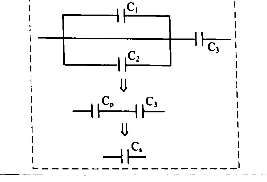
- Standard board result: two capacitors and in parallel, the combination then in series with . First ; then
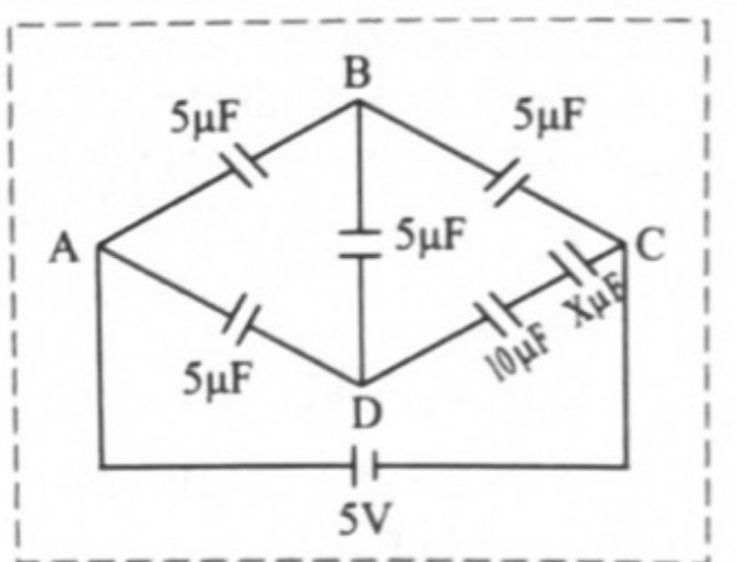
- For a bridge network of capacitors, the balance condition is . When balanced, the bridge arm carries no charge and can be removed, leaving two series paths in parallel.
Theory Questions Asked on This Subtopic
Real board questions. Answers are at the end of the page.
- 1
[Mar 19] Define capacitance of a capacitor and its S.I. unit.
Maharashtra HSC board questionAnswer 1 ↓ - 2
[Feb 23] Obtain an expression for equivalent capacitance of two capacitors C₁ and C₂ connected in series.
 Maharashtra HSC board questionAnswer 2 ↓
 - 3
[July 23] Two capacitors of capacities C₁ and C₂ are connected in parallel and this combination is connected in series with a capacitor of capacity C₃. Calculate the equivalent capacity of the combination of capacitors.
 Maharashtra HSC board questionAnswer 3 ↓
Numericals
Every numerical set on this subtopic. Full working is at the end of the page.
- 4
[Mar 08] A parallel plate air condenser has an area m² and separation between the two plates is 1 mm. Find its capacity. [ C²/Nm²]
Maharashtra HSC board questionAnswer 4 ↓ - 5
[Oct 09] A parallel plate capacitor has circular plates, each of diameter 20 cm separated by a distance of 2 mm. The potential difference between the plates is maintained at 360 V. Calculate its capacitance and charge. What is the intensity of electric filed between the plates of the capacitor? (Given: k = 1)
Maharashtra HSC board questionAnswer 5 ↓ - 6
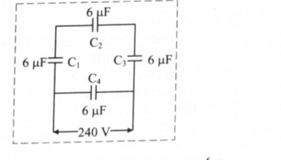
[Mar 14] A network of four capacitors of 6 μF each is connected to a 240 V supply. Determine the charge on each capacitor.
 Maharashtra HSC board questionAnswer 6 ↓
 - 7
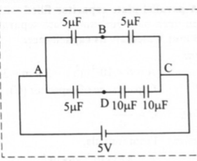
[Oct 14] Six capacitors of capacities 5, 5, 5, 5, 10 and X μF are connected as shown in the network given below. Find: i. The value of X if the network is balanced, and ii. The resultant capacitance between A and C.
 Maharashtra HSC board questionAnswer 7 ↓
 - 8
[July 17] Three capacitors of capacities 8 μF, 8 μF and 4 μF are connected in a series and potential difference of 120 volt is maintained across the combination. Calculate the charge on capacitor of capacity 4 μF.
Maharashtra HSC board questionAnswer 8 ↓ - 9
[Mar 22] A parallel plate capacitor filled with air has an area of 6 cm² and plate separation of 3 mm. Calculate its capacitance.
Maharashtra HSC board questionAnswer 9 ↓ - 10
[Feb 24] Two capacitors of capacities 5 μF and 10 μF respectively are connected in series. Calculate the resultant capacity of the combination.
Maharashtra HSC board questionAnswer 10 ↓
Answers & Solutions
Work the questions above first, then check yourself here. Each answer is set out the way it should be written in the paper.
i. The ability of a conductor to store the electric charge is called capacitance of conductor. ii. SI unit of capacity of conductor is farad (F). Thus, the capacity of a conductor is said to be 1 farad if the potential difference across it rises by 1 volt, when 1 C charge is given to it.
i. Diagram: ii. Explanation: a. Capacitors are said to be connected in series if they are connected one after the other in the form of a chain. b. Let capacitors of capacitances C₁, C₂ be connected in series as shown in the figure. c. Let V₁, V₂ be the corresponding potential differences in the capacitors. d. Suppose a potential difference 'V' is applied across the combination. The left plate of capacitor C₁ has a charge +Q. An equal but opposite charge −Q is induced on the right plate of this capacitor. This charge −Q induces a charge +Q on the left plate of C₂. e. Thus, each capacitor receives a magnitude of charge Q. Hence, when the capacitors are connected in series, same current flows through them and all have the same charge +Q induced on the plate. Thus, potential difference induced across capacitors is given by, f. Total potential difference 'V' across the combination is given by, g. If these capacitors are replaced by a single capacitor of capacity , such that effective capacity remains same then From equation (2) and (3),
When the capacitors C₁ and C₂ are connected in parallel, the effective capacitance is Now, when is connected in series with , we get the effective capacitance as
Given: A = m², d = 1 mm = m, C²/Nm² To find: Capacitance (C) Formula: Calculation: From formula, Ans: Capacity of given capacitor is 1.77 μμF.
Given: Diameter = 20 cm radius = 10 cm = 0.1 m, d = 2mm = m, V = 360 V, k = 1 To find: i. Capacitance (C) ii. Charge (Q) iii. Electric field intensity (E) Formulae: i. ii. iii. Calculation: From formula (i), From formula (ii), From formula (iii), Ans: i. Capacitance is F. ii. Charge is C. iii. Electric field intensity is V/m.
Given: F, V = 240 V To find: The charge on each capacitor (, , and ) Formulae: i. ii. iii. Calculation: The equivalent network for the given circuit is as follows: Using formula (i), equivalent capacity of three capacitors in series, is connected in parallel to the combination of , and . Using formula (ii), Equivalent capacitance, F Let potential across , , be given by , , respectively. Also, Hence, . Also charges , , on , , respectively are same. Using formula (iii), The charge on capacitor is and is given by, Ans: The charge on , , is C and that on is C.
Given: A balanced network of capacitors with , To find: i. The value of X ii. Resultant capacitance between A and C () Formulae: i. ii. (For balance condition) iii. Calculation: For branch DC of the given network, using formula (i), Now using formula (ii), As the network is balanced, the circuit can be reduced as follows: For path ABC, For part ADC, using formula (iii) Hence, Ans: i. The value of X is 10 μF. ii. The resultant capacitance between A and C is 5 μF.
Given: , , , V = 120 volt To find: Charge on the capacitor Formulae: i. ii. Calculation: Using formula (i), In series combination, Using formula (ii), Ans: The charge on the capacitor is C.
Given: A = m², r = 3 mm = m To find: Capacitance of capacitor (C) Formulae: Calculation: From formula, Ans: Capacitance is 1.77 pF.
When capacitors are connected in series,