Chapter 10
Magnetic Fields due to Electric Current
Maharashtra HSC · 13 subtopics · textbook pages 230–250
Formula SheetEvery formula this chapter can be examined on, in one table.
Constants, units and conventions
| Formula | Symbols, units and conditions |
|---|---|
| |
|
Magnetic force and the Lorentz force
| Formula | Symbols, units and conditions |
|---|---|
| |
| |
| |
|
Cyclotron motion
| Formula | Symbols, units and conditions |
|---|---|
| |
| |
| |
| |
| |
| |
| |
|
Helical motion
| Formula | Symbols, units and conditions |
|---|---|
| |
| |
|
Magnetic force on a current-carrying wire
| Formula | Symbols, units and conditions |
|---|---|
| |
| |
| |
| |
|
Force on a closed circuit in a uniform field
| Formula | Symbols, units and conditions |
|---|---|
|
Torque on a current loop; moving coil galvanometer
| Formula | Symbols, units and conditions |
|---|---|
| |
| |
| |
| |
|
Magnetic dipole moment
| Formula | Symbols, units and conditions |
|---|---|
| |
| |
|
Magnetic potential energy of a dipole
| Formula | Symbols, units and conditions |
|---|---|
| |
|
Biot-Savart law and the straight wire
| Formula | Symbols, units and conditions |
|---|---|
| |
| |
| |
| |
|
Force between two long parallel wires
| Formula | Symbols, units and conditions |
|---|---|
| |
| |
| |
|
Field due to a circular arc
| Formula | Symbols, units and conditions |
|---|---|
| |
| |
|
and 10.14 Circular loop: axial field and field lines
| Formula | Symbols, units and conditions |
|---|---|
| |
| |
| |
| |
|
Ampere's circuital law
| Formula | Symbols, units and conditions |
|---|---|
| |
| |
| |
| |
| |
|
Solenoid and toroid
| Formula | Symbols, units and conditions |
|---|---|
| |
|
Results the exercises set
| Formula | Symbols, units and conditions |
|---|---|
| |
| |
|
Short NotesThe chapter subtopic by subtopic, in the textbook's own order.13 subtopics
- 1Introduction
- 2Magnetic Force
- 3Cyclotron Motion3 board questions
- 4Helical Motion
- 5Magnetic Force on a Wire Carrying a Current
- 6Force on a Closed Circuit in a Magnetic Field1 board question
- 7Torque on a Current Loop6 board questions
- 8Magnetic Dipole Moment3 board questions
- 9Magnetic Field due to a Current: Biot-Savart Law3 board questions
- 10Force of Attraction between two Long Parallel Wires2 board questions
- 11Magnetic Lines for a Current Loop1 board question
- 12Ampere's Law2 board questions
- 13Magnetic Field of a Solenoid and a Toroid3 board questions
The whole chapter in brief
What the chapter is about
- Oersted first showed that a current produces a magnetic field; Gauss, Henry, Faraday and Maxwell established that electric and magnetic fields are partners. Motors, generators, communication systems and computers all follow from it.
- Two parallel hanging wires attract when the currents are in the same direction and repel when they are opposite. The forces are not electrostatic — the wires stay electrically neutral throughout, so the origin must be magnetic.
- Right hand thumb rule: grab the wire with the right hand, thumb along the current; the curled fingers give the direction of the circular magnetic field lines.
- Notation: means out of the plane of the paper, means into it.
10.2 Magnetic force and the Lorentz force
- Magnetic force on a charge moving with velocity in a field : . For an electron .
- Magnitude , direction perpendicular to the plane containing and .
- Lorentz force (both fields present): .
- Consequences: (i) if is parallel (or antiparallel) to , ; (ii) if the charge is stationary, even when .
- Because , : the magnetic force never does work. It can change the direction of motion but never the speed or the kinetic energy.
- The electric force depends only on and ; the magnetic force depends on , on the speed, and on the angle between and .
- Unit of : from , 1 tesla = 1 N s / (C m). gauss.
10.3 Cyclotron motion
- In a uniform field perpendicular to its velocity a charged particle moves in a circle, the magnetic force supplying the centripetal force: , hence (the cyclotron formula).
- Radius ; period ; cyclotron frequency .
- The key fact: and do not depend on the speed or on the radius. The particle takes the same time for every semicircle however fast it goes.
10.3.1 The cyclotron accelerator
- Invented by Lawrence and Livingston in 1934 to study nuclear structure; accelerates charged particles to MeV-GeV energies for particle-matter interaction studies and for treating certain tumours.
- Construction: two hollow semicircular metal chambers, the dees and , placed in a vacuum chamber, with a uniform magnetic field (up to about 1.5 T) perpendicular to their plane, and a high-frequency alternating voltage (up to 10000 V, about 10 MHz) applied across the gap between them. An ion source sits at O in the gap. The electric and magnetic fields are perpendicular to each other — crossed fields.
- Working: the magnetic field bends the ion into a semicircle inside a dee (there is no electric field inside a dee); each time it crosses the gap the alternating field accelerates it, adding to its kinetic energy; the radius grows each time, so the path is a spiral. At the largest radius it is deflected out through an exit slit.
- Resonance condition: , so that the polarity of the dees reverses exactly as the ion reaches the gap. The interval after which the field must be reversed is .
- Final energy: , proportional to the square of the outermost radius.
- Accelerators in India: the 2 GeV electron Synchrotron at RRCAT, Indore, and the 8-10 MeV Microtron at Savitribai Phule Pune University.
10.4 Helical motion
- If the velocity has a component along , then for that component , so it is unaffected and the particle drifts steadily along the field.
- The perpendicular component produces the circular motion as before.
- The two together give a helix: circular motion in the plane perpendicular to superposed on uniform translation along .
- Radius ; period (unchanged); pitch .
10.5 Magnetic force on a wire carrying a current
- Straight wire, field perpendicular: the drifting electrons each feel ; with this gives .
- If is not perpendicular to the wire, , magnitude , where points along the current.
- Arbitrarily shaped wire: and .
- For uniform : — only the straight line joining the two ends matters.
- Diagram (Fig. 10.8): a vertical wire in the plane of the page carrying current upward, field shown as dots coming out of the page, electrons drifting downward with velocity , and the resulting force marked horizontally, perpendicular to both.
10.6 Force on a closed circuit in a magnetic field
- Extending the wire result to a closed circuit C: for uniform .
- The sum of the length vectors right round a closed circuit is zero.
- Therefore the net force on a closed circuit placed in a uniform magnetic field is zero. This is a standard one-mark question — the answer is simply "zero".
- Careful: zero net force does not mean zero net torque. A current loop in a uniform field usually experiences a couple.
10.7 Torque on a current loop
- Take a rectangular loop abcd, sides (ab, cd) and (bc, da), carrying current in a uniform field , with ab and cd perpendicular to . Let be the angle between the normal to the plane of the loop and .
- Forces on bc and da: each. They are equal, opposite and act along the same line, so they cancel completely and produce no torque.
- Forces on ab and cd: each. They are equal and opposite but do not act along the same line, so they form a couple. Moment arm of each about the central axis is .
- Torque .
- For a flat coil of turns: . This holds for a planar coil of any shape in a uniform field.
- This is the principle of an electric motor. To keep the coil rotating past the position where its plane is parallel to , a commutator with carbon brushes reverses the current every half rotation, so the torque keeps turning the coil the same way.
10.7.1 Moving coil galvanometer
- Principle: when a coil carrying a current is suspended in a uniform magnetic field, a torque acts on it, tending to rotate it about the axis of suspension so that the magnetic flux through the coil becomes maximum.
- Construction and working, as the board wants it: (i) a coil of several turns, suspended or pivoted so that it can rotate freely about a fixed axis in a radial uniform magnetic field; (ii) a soft iron cylindrical core makes the field radial and strong; (iii) current through the coil produces , and since the field is radial , so ; (iv) a spring provides a counter torque, so a steady current gives a steady deflection ; (v) the restoring torque of the spring is , with the torsional constant.
- At equilibrium , so , i.e. . A galvanometer therefore has a linear (uniform) scale.
- Diagram: a rectangular coil of turns wound on a frame, suspended by a phosphor bronze strip between the concave pole pieces of a permanent magnet, with a soft iron cylindrical core between the poles; a spring at the bottom, a pointer or mirror to read the deflection, and terminals for the current.
10.8 Magnetic dipole moment
- A current carrying coil behaves as a magnetic dipole with moment (also written ), directed along the normal to the plane of the coil, sense given by the right-hand thumb rule.
- Magnitude ; SI unit A m, equivalently J/T.
- Torque on it in a uniform field: , or in vector form — the exact analogue of for an electric dipole.
- For a single loop, .
10.9 Magnetic potential energy of a dipole
- A dipole freely suspended in a field has potential energy on account of its orientation: , analogous to .
- Case (i): gives , the minimum — parallel to , the stable orientation.
- Case (ii): gives , the maximum — antiparallel to .
10.10 Biot-Savart law
- Statement: the magnitude of the field at a point P due to a current element is , where is the distance of P from the element and the angle between and .
- Vector form: . The direction of is that of .
- T m/A T m/A.
- It is still an inverse square law: in the numerator cancels one power of the below.
- Biot-Savart law plays the role in magnetostatics that Coulomb's law plays in electrostatics.
- Long straight wire, perpendicular distance : integrating over the whole wire (substitute ) gives . Half of the wire alone (semi-infinite) gives .
10.11 Force between two long parallel wires
- Wire 1 produces at wire 2. The Lorentz force law then gives, on a length of wire 2, .
- Force per unit length: .
- Parallel currents attract; antiparallel currents repel. , consistent with Newton's third law.
- Definition of the ampere: two infinitely long parallel wires 1 m apart in vacuum, each carrying the same constant current, experience a force of N per metre of length; that current is 1 ampere.
- Note that for infinitely long wires the total force would be infinite, which is why the result is always quoted per unit length.
10.12 Field due to a current in a circular arc
- On an arc, is always perpendicular to , so and every element contributes in the same sense at the centre.
- at the centre, with the subtended angle in radians.
- Semicircle: . Full circle: .
- Straight sections in line with the centre contribute nothing, because . That is the whole trick in the "two straight sections and one arc" problems.
10.13 Axial field of a circular current loop
- Loop of radius in the x-y plane, centre at the origin, point P on the z axis at distance ; and every is perpendicular to .
- Components of perpendicular to the axis cancel in pairs from diametrically opposite elements; only the z components survive, with and .
- Result: .
- Setting : , and for turns .
10.14 Magnetic lines for a current loop
- Diagram (Fig. 10.20): closed loops that pass through the ring, crowded and nearly straight along the axis inside, spreading out and returning round the outside — exactly the pattern of a short bar magnet.
- Right hand thumb rule for a loop: curl the fingers of the right hand along the current in the wire; the stretched thumb points along the field on the axis, i.e. towards the north face.
- The face from which the field lines emerge behaves as the north pole, the other face as the south pole.
- For : , with . So at large distances a current loop is a magnetic dipole. and point the same way.
- By the electrostatic analogue, on the perpendicular bisector for .
- Fundamental difference between an electric and a magnetic dipole: an electric dipole can be split into two isolated charges, but a magnetic dipole cannot be split into isolated poles — no magnetic monopole has ever been found.
10.15 Ampere's circuital law
- Statement: the line integral of the magnetic induction around any closed path in free space equals times the total current flowing through the area bounded by the path: .
- The closed path is called the Amperian loop; is the net current it encircles.
- Since , the law is an integral of the tangential component of round the loop.
- Sign convention: curl the right palm along the loop with the fingers in the direction of integration; a current parallel to the stretched thumb is positive, one opposite to it negative. For the standard figure with out of the page, into the page and outside the loop: . contributes nothing, as its contributions cancel over the full loop.
- Ampere's law plays the role in magnetostatics that Gauss' law plays in electrostatics; it can be derived from the Biot-Savart law and is at its most useful when the current distribution is symmetric.
- Long straight wire: take a circle of radius round the wire, on which is constant and tangential, so and , giving .
10.16 Solenoid
- A solenoid is a long, closely wound helical coil whose diameter is much smaller than its length.
- Inside, the field lines are dense, parallel and uniform along the axis; outside they are widely spaced, so the field there is weak. In an ideal solenoid (infinite length, square cross-section wire, very closely wound) the field inside is uniform and along the axis, and outside it is exactly zero.
- Derivation: take a rectangular Amperian loop abcd with side ab of length inside and parallel to the axis, cd outside, bc and da perpendicular to the axis. Then . The bc and da integrals vanish because there; the cd integral vanishes because outside. So .
- With turns per unit length and current , the current enclosed is , so and .
- Valid for a real solenoid too at points near the middle, but not near its ends.
10.16 Toroid
- A toroid is a solenoid of finite length bent into a hollow circular tube, like the inner tube of a tyre.
- The field lines inside are concentric circles; the direction of at a point is along the tangent to the circle through that point, fixed by the direction of the current.
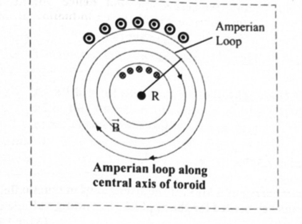
- Derivation: take a circular Amperian loop of radius along the central axis of the tube. Here and are in the same direction, so , , and . The net enclosed current is , so and .
- Since , the field is not constant over the cross-section of a toroid — unlike a solenoid. For an ideal toroid, everywhere outside.
Electrostatic - magnetostatic analogy
| Electrostatics | Magnetostatics |
|---|---|
| Coulomb's law | Biot-Savart law |
| Gauss' law | Ampere's circuital law |
| Electric dipole moment | Magnetic dipole moment |
| Axial field | Axial field |
| Equatorial field | Equatorial field |
Distinguish between: electric force and magnetic force on a charge
| Electric force | Magnetic force |
|---|---|
| Acts on a charge whether it moves or not | Acts only on a moving charge |
| Independent of the direction of motion | Depends on the angle between and |
| Along (or opposite to) | Perpendicular to both and |
| Does work; changes speed and kinetic energy | Does no work; changes direction only |
Distinguish between: Biot-Savart law and Ampere's law
| Biot-Savart law | Ampere's circuital law |
|---|---|
| Field of a single current element, summed by integration | Field found from the net current enclosed by a loop |
| Works for any current distribution, symmetric or not | Practical only when the distribution is symmetric |
| Magnetostatic analogue of Coulomb's law | Magnetostatic analogue of Gauss' law |
Distinguish between: solenoid and toroid
| Solenoid | Toroid |
|---|---|
| Straight helical coil, length much greater than diameter | Solenoid bent into a closed circular ring |
| inside | along the central axis |
| Field uniform inside, independent of position across the section | Field varies as , not uniform across the section |
| Field lines straight inside, closing outside; outside an ideal solenoid | Field lines are closed concentric circles inside; outside an ideal toroid |
| Has identifiable north and south ends | Has no free ends and no poles |
Traps that cost marks
- Magnetic force does no work. If a question asks what happens to the kinetic energy of a charge entering a magnetic field perpendicular to , the answer is that it remains unchanged.
- in is measured from the normal to the plane of the coil, not from the plane. When the question says "the axis of the coil is inclined at to ", the axis is the normal, so . Read the wording of the paper carefully: board solutions have used this conversion.
- In the cyclotron the quantity asked for is almost always the half period , the interval between field reversals — not the full period .
- in is turns per metre, not the total number of turns. Divide by the length first. Two layers of windings of 500 turns each means .
- In the toroid formula , is the total number of turns, not turns per unit length, and is the radius of the Amperian circle (the mean radius of the tube).
- Do not mix up (long straight wire) with (centre of a circular loop). One has in it, the other does not.
- Net force on a closed circuit in a uniform field is zero, but the net torque is generally not zero. Do not write that both vanish.
- Convert centimetres and millimetres to metres, and diameter to radius, before substituting. Circular coil problems usually give the diameter.
- A straight wire segment produces no field at a point lying on the line of the wire produced, because there. Do not attempt to add a contribution from it.
- Ampere's law counts only the current enclosed by the Amperian loop; a current outside contributes zero to the line integral, even though it does contribute to at points on the loop.
- Parallel currents attract, antiparallel currents repel. This is the opposite of the like-charges rule from electrostatics, and it is easy to write down backwards.
- State the units: in tesla (or Wb/m), in A m (or J/T), in N m, in N/m. Marks are given for units in numericals.
Solved Numerical ExamplesWorked numericals to attempt first, each with a hint before the full solution.Coming soon
These are being added chapter by chapter. They are solved numericals from the prescribed book and the reference guides — not previous board questions, which live under Practice — so that you can work through the method before meeting it in a real paper.
Important DerivationsEvery derive / obtain / prove question in this chapter. 3 have come up in two or more papers.6
- 1Orbital magnetic moment of an electron revolving around the nucleus (and Bohr magneton) RepeatsDerive an expression for the orbital magnetic moment of an electron revolving around the nucleus in an atom. State the formula for the Bohr magneton.
Asked in: March 2014; October 2014; February 2020; July 2022 (Q.19, 3 marks); July 2023 (Q.20, 3 marks)
Show the derivationHide the derivation
Expression for magnetic dipole moment:Step 1Consider an electron of mass and charge e revolving in a circular orbit of radius r around the positive nucleus in clockwise direction, leading to an anticlockwise current.Step 2If the electron travels a distance in time T then, its orbital speedStep 3Magnitude of circulating current is given by,But,Step 4The orbital magnetic moment associated with orbital current loop is given by,Step 5The angular momentum of an electron due to its orbital motion is given by,Step 6Multiplying and dividing the R.H.S of equation (2) by ,Step 7This equation shows that orbital magnetic moment is proportional to the angular momentum. But as the electron bears negative charge, the orbital magnetic moment and orbital angular momentum are in opposite directions and perpendicular to the plane of the orbit.Using vector notation,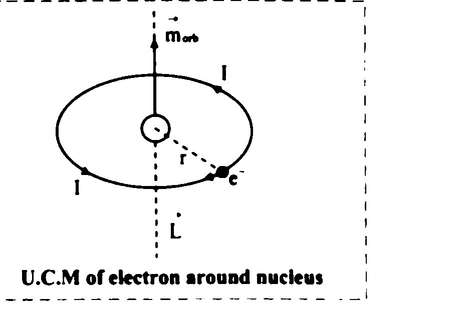
- 2Magnetic induction of a toroid (N turns) RepeatsObtain an expression for magnetic induction of a toroid of 'N' turns about an axis passing through its centre and perpendicular to its plane.
Asked in: March 2014; February 2023 (Q.4, 2 marks)
Show the derivationHide the derivation
StatementThe line integral of magnetic field of induction around any closed path in free space is equal to absolute permeability of free space times the total current flowing through area bounded by the path.Mathematically,The sign indicates that the integral is to be evaluated over a closed loop called Amperian loop. The current I on the right hand side is the net current encircled by the Amperian loop.Explanation:Step 1Consider cross-sections of four long straight wires carrying currents , , , into or out of the plane of the paper are shown in figure below.Step 2An Amperian loop is drawn to encircle 3 of the current wires and not the fourth one.Step 3As the current goes perpendicular to the plane of the paper, is in the plane of the paper even if its direction is unknown.Step 4The length element on the Amperian loop is (in the plane of the paper).Using Ampere's law,Step 5Thus the integration is over the product of length dl of the Amperian loop and the component of the magnetic field B cos θ, tangent to the loop.Step 6Using curled palm right hand thumb rule, for the distribution of currents as shown and are coming out of the paper, (⊙) parallel to the stretched thumb. Hence these are positive. , on the other hand is going into the plane of the paper (⊗). Thus, it is negative.The Current is not within the Amperian loop. As the integration is over a full loop, contributions of to B cancel out.Expression for magnetic induction at a point along the axis of a toroid:Step 1Consider a toroid carrying steady current I and having turns N.Step 2The magnetic field around the toroid consists of concentric circular lines of force around it. Magnetic field is produced, when a steady current 'I' flows through toroid.Step 3The direction of magnetic field at a point is along the tangent to the circular path at that point.Step 4Let R be the radius of the Amperian loop. This loop is concentric with the axis of toroid. P is a point on the loop.Step 5Applying Ampere's law,where,N = total number of turns in the toroid.I = total current flowing through toroid.i = Current flowing in each turnNow,Step 6But, and are in same directionEquation (2) can be written as,Step 7Also....(total length of circle is its circumference)From equation (3),Step 8From equation (1) and (4),This is the required expression.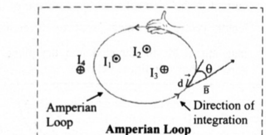
- 3Shunt resistance for a moving-coil galvanometer,For a moving coil galvanometer, show that , where S is shunt resistance, G is galvanometer resistance, n is the ratio of total current to the full scale deflection current.
Asked in: July 2023 (Q.9, 2 marks)
Show the derivationHide the derivation
Step 1To use a M.C.G as an ammeter, a shunt (low resistance) is connected in parallel to the coil of M.C.G.Step 2In the arrangement as shown in the figure, I and are the current through the circuit and galvanometer respectively.Therefore, the current through shunt S is,Step 3Since S and G are parallel, potential difference across them is same.Equation (1) is useful to calculate the range of current that the galvanometer can measure.Step 4If the current I is n times current , then . Using this in equation (1),This is the required shunt to increase the range n times.Step 5If is the current through the shunt resistance, then the remaining current will flow through galvanometer.This equation gives the fraction of the total current through the shunt resistance.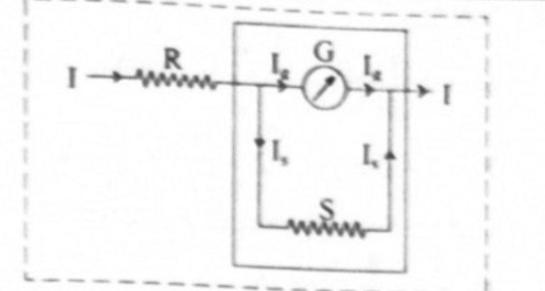
- 4Deflection of a moving-coil galvanometer is proportional to the currentShow that the deflection produced in a moving coil galvanometer is directly proportional to the current flowing through its coil or vice-versa.
Asked in: July 2023 (Q.16, 3 marks)
Show the derivationHide the derivation
[From 10.7, Q1]Principle of M.C.G:When a coil carrying an electric current is suspended in a uniform magnetic field, a torque acts on it. This torque tends to rotate the coil about the axis of suspension so that the magnetic flux passing through the coil is maximum.Working:Step 1M.C.G. consists of a coil of several turns mounted (suspended or pivoted) in such a way that it can freely rotate about a fixed axis, in a radial uniform magnetic field.Step 2A soft iron cylindrical core makes the field radial and strong.Step 3The coil rotates due to a torque acting on it as the current flows through it. Torque acting on current carrying coil is .Here as the field is radial.where A is the area of the coil, B the strength of the magnetic field, N the number of turns of the coil and I the current in the coil.Step 4This torque is counter balanced by a torque due to a spring fitted at the bottom so that a fixed steady current I in the coil produces a steady angular deflection φ.Step 5Larger the current is, larger is the deflection and larger is the torque due to the spring. If the deflection is φ, the restoring torque due to the spring is equal to Kφ where K is the torsional constant of the spring.Thus, Kφ = NIAB,This means, the deflection φ is proportional to the current I i.e., .Working [(iii), (iv), and (v)] - 5Force on a closed circuit of arbitrary shape in a uniform magnetic fieldAssuming an equation of magnetic force due to an arbitrarily shaped wire, obtain an expression for force on a closed circuit in a uniform magnetic field.
Asked in: June 2025 (Q.7, 2 marks)
Show the derivationHide the derivation
The question is a real board question. This working is ours — no source printed a derivation for it.
Diagram
Draw a closed loop of arbitrary (irregular) shape carrying a current , placed in a uniform magnetic field shown by equally spaced parallel arrows. Mark a small element of the wire on the loop, with the current direction arrowed along it, and label the start and end points of the circuit as the same point .
Starting point
For a small element of a wire carrying current in a magnetic field , the force is
For a wire of arbitrary shape the total force is the sum of these over the whole wire:
Derivation
The current is the same at every point of a series circuit, and the field is uniform, so both and are constants and can be taken outside the integral:
The circle on the integral is the point: the circuit is closed, so the path starts and ends at the same point . The vector sum of the small displacements around a closed path is the displacement from back to , which is the null vector:
Hence
Conclusion
The net magnetic force on **any** closed circuit of any shape placed in a **uniform** magnetic field is zero, whatever the current and whatever the orientation.
Two cautions worth writing:
- Zero net force does not mean zero torque. A current loop in a uniform field
generally experiences a couple, , which is what turns the coil of a motor and of a moving-coil galvanometer.
- The result depends on the field being uniform. In a non-uniform field
cannot come out of the integral and the net force is generally not zero.
- 6Magnetic field at the centre of a circular arc of current-carrying wire (Biot-Savart law) RepeatsDerive an expression for the magnetic field produced at the centre of a circular arc of a wire carrying current I.
Asked in: June 2025 (Q.20, 3 marks); February 2026 (Q.9, 2 marks)
Show the derivationHide the derivation
The question is a real board question. This working is ours — no source printed a derivation for it.
Diagram
Draw a circular arc of radius with its centre at , subtending an angle at , carrying current . Mark a small element on the arc, the position vector from that element to , and the angle between them. Show the resulting field at as an arrow perpendicular to the plane of the paper (into the page for a clockwise current), with the two straight radial leads drawn along and .
Starting point — the Biot-Savart law
The magnetic induction at a point due to a current element at a position from it is
Derivation
Take the point at the centre of the arc. Every element of the arc is a tangent to the circle, and the line joining it to the centre is a radius, so the two are always perpendicular:
Every element is also at the same distance from . Therefore
By the right-hand rule, from every element of the arc points the same way — perpendicular to the plane of the arc — so the contributions add as scalars rather than as vectors:
The integral is simply the length of the arc, and an arc of radius subtending an angle (in radians) at the centre has length :
Special cases
- **Full circular loop**, :
.
- **Semicircle**, : .
- **Quarter circle**, : .
The straight radial leads running to and from the centre contribute nothing, because for them is along and .
Finished revising this chapter? Practise Magnetic Fields due to Electric Current →