10.15
Ampere's Law
Magnetic Fields due to Electric Current · Maharashtra HSC
Theory
Why the law is needed
In electrostatics, a symmetric distribution of charges — planar, spherical or cylindrical — lets you find the electric field far more easily with Gauss' law than by summing Coulomb contributions. The same is true here for a distribution of currents (not charges). Where the currents have some symmetry, Ampere's law gives the magnetic field with fair ease, and it becomes unnecessary to evaluate the integrals of the Biot-Savart law.
Ampere's law can itself be derived from the Biot-Savart law. It is named after Andre Marie Ampere (1775-1836), after whom the SI unit of current is named.
Ampere's law plays the role in magnetostatics that Gauss' law plays in electrostatics, just as the Biot-Savart law plays the role that Coulomb's law plays.
Statement
The line integral of the magnetic field of induction around any closed path in free space is equal to the absolute permeability of free space times the total current flowing through the area bounded by the path.
Mathematically,
The sign indicates that the integral is to be evaluated over a closed loop, called the Amperian loop. The current on the right hand side is the net current encircled by the Amperian loop.
Explanation
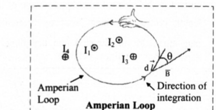
Diagram (Fig. 10.22): the cross-sections of four long straight wires are drawn as small circles in the plane of the paper, carrying currents , , , into or out of the plane. and are marked (out of the paper), is marked (into the paper). An irregular closed Amperian loop is drawn so that it encircles the wires carrying , and but leaves outside it. An element is marked on the loop, with at that point making an angle with it.
- Consider the cross-sections of four long straight wires carrying currents , , , into or out of the plane of the paper.
- An Amperian loop is drawn to encircle three of the current carrying wires and not the fourth one.
- As the currents go perpendicular to the plane of the paper, lies in the plane of the paper, even if its direction is not known in advance.
- The length element on the Amperian loop is , also in the plane of the paper. Therefore , and using Ampere's law,
- So the integration is over the product of the length of the Amperian loop and the component of the magnetic field tangent to the loop.
Sign convention for the enclosed currents
Use the curled-palm right hand rule. Curl the right hand palm along the Amperian loop with the fingers in the direction of integration. Then a current in the direction of the stretched thumb is assigned a positive sign, and a current in the direction opposite to the stretched thumb is assigned a negative sign.
For the distribution shown, and come out of the paper (), parallel to the stretched thumb, so they are positive; goes into the plane of the paper (), so it is negative. Hence
The current is not within the Amperian loop. As the integration is over a full loop, the contributions of to cancel out, and it does not appear on the right hand side.
Application: magnetic induction near a long straight current carrying conductor
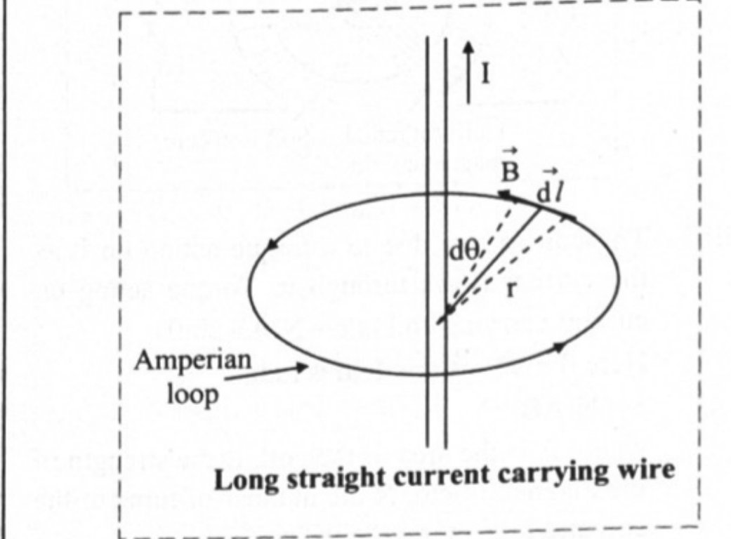
Diagram (Fig. 10.23): a long straight wire carrying a current , perpendicular to the plane of the paper. A circular Amperian loop of radius is drawn concentric with the wire in the plane of the paper. At every point of the circle and are tangential to the loop and in the same direction.
Since and are tangential to the Amperian loop, which here is a circle,
By symmetry has the same magnitude at every point of the circle, so
Equating this to by Ampere's law,
This is the required expression. It agrees with the result obtained earlier by direct integration of the Biot-Savart law, and it shows that the field of an infinitely long wire is proportional to the current and inversely proportional to the distance from the wire. The direction of is circular round the wire, given by the right hand thumb rule.
Application: coaxial cable (textbook Example 10.7)
A coaxial cable has a central conducting core wire of radius and a coaxial cylindrical outer conductor of radius ; the two carry equal currents in opposite directions.
By symmetry is tangent to any circle centred on the central conductor.
For , the loop encloses only the core current :
For , the loop encloses both conductors, whose currents are equal and opposite, so the net enclosed current is zero:
Application: current density inside a thick wire
For a long cylindrical wire of radius carrying a current along its axis, take a circular Amperian loop of radius inside the wire; then .
- Uniform current density : , so .
- Current density varying as : integrating, , so .
Standard results
- ; the loop is the Amperian loop
- Sign of each enclosed current from the curled-palm right hand rule; currents outside the loop contribute nothing
- Long straight wire:
- Coaxial cable: for ; for
- Thick wire: (uniform ); (for )
- Ampere's law is easy to apply only when the current distribution is symmetric; otherwise use the Biot-Savart law.
Theory Questions Asked on This Subtopic
Real board questions. Answers are at the end of the page.
- 1
State and explain Ampere's circuital law.
 Maharashtra HSC board question — asked in March 2018Answer 1 ↓
 - 2
State Ampere's law and hence obtain an expression for the magnetic induction at any point near a straight conductor carrying a current. OR State Ampere's circuital law. Using Ampere's circuital law, obtain an expression for magnetic induction at any point due to a straight conductor carrying current.
 Maharashtra HSC board question — asked in July 2019; March 2009Answer 2 ↓
Answers & Solutions
Work the questions above first, then check yourself here. Each answer is set out the way it should be written in the paper.
Statement: The line integral of magnetic field of induction around any closed path in free space is equal to absolute permeability of free space times the total current flowing through area bounded by the path. Mathematically, The sign indicates that the integral is to be evaluated over a closed loop called Amperian loop. The current I on the right hand side is the net current encircled by the Amperian loop. Explanation: i. Consider cross-sections of four long straight wires carrying currents , , , into or out of the plane of the paper are shown in figure below. ii. An Amperian loop is drawn to encircle 3 of the current wires and not the fourth one. iii. As the current goes perpendicular to the plane of the paper, is in the plane of the paper even if its direction is unknown. iv. The length element on the Amperian loop is (in the plane of the paper). Using Ampere's law, v. Thus the integration is over the product of length dl of the Amperian loop and the component of the magnetic field B cos θ, tangent to the loop. vi. Using curled palm right hand thumb rule, for the distribution of currents as shown and are coming out of the paper, (⊙) parallel to the stretched thumb. Hence these are positive. , on the other hand is going into the plane of the paper (⊗). Thus, it is negative. The Current is not within the Amperian loop. As the integration is over a full loop, contributions of to B cancel out.
[From 10.15, Q1 (Statement only)] Statement: The line integral of magnetic field of induction around any closed path in free space is equal to absolute permeability of free space times the total current flowing through area bounded by the path. Mathematically, The sign indicates that the integral is to be evaluated over a closed loop called Amperian loop. The current I on the right hand side is the net current encircled by the Amperian loop. Explanation: i. Consider cross-sections of four long straight wires carrying currents , , , into or out of the plane of the paper are shown in figure below. ii. An Amperian loop is drawn to encircle 3 of the current wires and not the fourth one. iii. As the current goes perpendicular to the plane of the paper, is in the plane of the paper even if its direction is unknown. iv. The length element on the Amperian loop is (in the plane of the paper). Using Ampere's law, v. Thus the integration is over the product of length dl of the Amperian loop and the component of the magnetic field B cos θ, tangent to the loop. vi. Using curled palm right hand thumb rule, for the distribution of currents as shown and are coming out of the paper, (⊙) parallel to the stretched thumb. Hence these are positive. , on the other hand is going into the plane of the paper (⊗). Thus, it is negative. The Current is not within the Amperian loop. As the integration is over a full loop, contributions of to B cancel out. Expression for magnetic induction at any point due to a straight conductor carrying current: i. Consider a long straight wire carrying a current I as shown in figure below. and are tangential to the Amperian loop which in this case is a circle. ii. The field at a distance r from the wire is given by This is the required expression.