10.7
Torque on a Current Loop
Magnetic Fields due to Electric Current · Maharashtra HSC
Theory
Set-up and diagram
Diagram (Fig. 10.10 and Fig. 10.11): a rectangular current carrying loop abcd is placed in a uniform magnetic field , with the sides ab and cd perpendicular to and the sides bc and da not. Label ab and cd as the sides of length , and bc and da as the sides of length . Current circulates round the loop. The magnetic forces on ab and cd are drawn as an equal and opposite pair, one up and one down out of the plane containing , so that the loop turns about its central axis.
Figure 10.12 is the side view: the loop seen edge-on, with the normal to its plane making an angle with , and the moment arms marked.
Let be the angle between the normal to the plane of the loop and the direction of .
Forces on the four sides
Sides 2 (da) and 4 (bc): the angle between the current direction and here is , so
and is equal and opposite to . Both act along the same line, so they cancel out completely and contribute no torque.
Sides 1 (cd) and 3 (ab): these are perpendicular to , so each experiences a force of magnitude
These two forces are equal and opposite but do not act along the same line. They therefore form a couple and produce a net torque, which rotates the loop until its plane is perpendicular to .
Torque
The moment arm of each force about the central axis of the loop is . Hence
with the area enclosed by the loop.
For a coil of turns,
This expression holds for all flat (planar) coils in a uniform magnetic field, whatever their shape.
Principle of the electric motor
The torque on a current carrying coil in a magnetic field is the working principle of an electric motor. To keep the coil turning through a full rotation, the current must be reversed each time the plane of the coil tends to become parallel to : when segment ab reaches the position of cd, the current is reversed so that it flows from a to b instead of b to a, and continues to act in the same sense, so the torque keeps turning the coil the same way. The reversal is achieved by a commutator, which connects the power supply to the coil through carbon brush contacts.
10.7.1 Moving coil galvanometer
Principle: when a coil carrying an electric current is suspended in a uniform magnetic field, a torque acts on it. This torque tends to rotate the coil about the axis of suspension so that the magnetic flux passing through the coil is maximum.
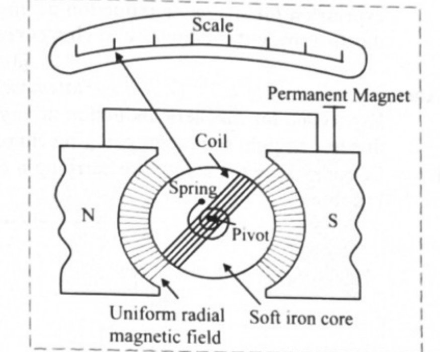
Diagram (Fig. 10.13): a rectangular coil of several turns wound on a light frame, suspended by a fine phosphor bronze strip between the concave pole pieces N and S of a permanent magnet; a soft iron cylindrical core sits between the poles inside the coil, making the field radial and strong; a hair spring at the lower end supplies the restoring torque; a pointer over a scale, or a mirror with a lamp and scale, reads the deflection; terminals carry the current in and out.
Working, in the board's own steps:
- The M.C.G. consists of a coil of several turns mounted (suspended or pivoted) so that it can rotate freely about a fixed axis, in a radial uniform magnetic field.
- A soft iron cylindrical core makes the field radial and strong.
- The coil rotates due to the torque acting on it as the current flows through it. The torque on a current carrying coil is . Here because the field is radial — the plane of the coil is always parallel to the field — so and , where is the area of the coil, the strength of the magnetic field, the number of turns and the current.
- This torque is counterbalanced by the torque due to a spring fitted at the bottom, so that a fixed steady current in the coil produces a steady angular deflection .
- The larger the current, the larger the deflection and the larger the restoring torque of the spring. If the deflection is , the restoring torque of the spring is , where is the torsional constant of the spring.
At equilibrium the two torques balance:
Since , , and are all constants for a given galvanometer, : the deflection produced is directly proportional to the current flowing through the coil. This is why a moving coil galvanometer has a uniform (linear) scale.
Rearranged for the current, .
Modern instruments use digital ammeters and voltmeters and no longer use a moving coil galvanometer.
Standard results
- Forces on the sides parallel to cancel along the same line; forces on the sides perpendicular to form a couple
- for one turn, for turns
- is measured between the normal to the plane of the coil and ; if the plane (or axis) angle is given instead, use
- when the plane of the coil contains ; when the plane is perpendicular to
- Galvanometer (radial field): , , ,
Theory Questions Asked on This Subtopic
Real board questions. Answers are at the end of the page.
- 1
State the principle of a moving coil galvanometer and explain its working.
 Maharashtra HSC board question — asked in March 2010; October 2008Answer 1 ↓
 - 2
Draw a neat and labelled diagram of suspended coil type moving coil galvanometer.
Maharashtra HSC board question — asked in March 2015Answer 2 ↓ - 3
Show that the deflection produced in a moving coil galvanometer is directly proportional to the current flowing through its coil or vice-versa.
Maharashtra HSC board question — asked in July 2023Answer 3 ↓
Numericals
Every numerical set on this subtopic. Full working is at the end of the page.
- 4
[July 18] A closely wound solenoid of 1000 turns and area of cross-section m² carries a current of 1 A. It is placed in a horizontal plane with its axis making an angle of 30° with the direction of uniform magnetic field of 0.16 T. Calculate the torque acting on the solenoid.
Maharashtra HSC board questionAnswer 4 ↓ - 5
[July 19] A coil has 'n' turns, each of cross-sectional area 1.6 cm². The axis of the coil is kept inclined at 30° with the direction of uniform magnetic field of induction 2 N/Am. The torque of 0.02 Nm is experienced by the coil, when a current of 1.25 A flows through each turn. Calculate n.
Maharashtra HSC board questionAnswer 5 ↓ - 6
[Feb 20] A moving coil galvanometer (M.C.G.) has 10 turns each of length 12 cm and breadth 8 cm. The coil of M.C.G. carries a current of 125 μA and is kept perpendicular to the uniform magnetic field of induction T. The twist constant of phosphor bronze fibre is Nm/degree. Calculate the deflection produced.
Maharashtra HSC board questionAnswer 6 ↓
Answers & Solutions
Work the questions above first, then check yourself here. Each answer is set out the way it should be written in the paper.
Principle of M.C.G: When a coil carrying an electric current is suspended in a uniform magnetic field, a torque acts on it. This torque tends to rotate the coil about the axis of suspension so that the magnetic flux passing through the coil is maximum. Working: i. M.C.G. consists of a coil of several turns mounted (suspended or pivoted) in such a way that it can freely rotate about a fixed axis, in a radial uniform magnetic field. ii. A soft iron cylindrical core makes the field radial and strong. iii. The coil rotates due to a torque acting on it as the current flows through it. Torque acting on current carrying coil is . Here as the field is radial. where A is the area of the coil, B the strength of the magnetic field, N the number of turns of the coil and I the current in the coil. iv. This torque is counter balanced by a torque due to a spring fitted at the bottom so that a fixed steady current I in the coil produces a steady angular deflection φ. v. Larger the current is, larger is the deflection and larger is the torque due to the spring. If the deflection is φ, the restoring torque due to the spring is equal to Kφ where K is the torsional constant of the spring. Thus, Kφ = NIAB, This means, the deflection φ is proportional to the current I i.e., .
[From 10.7, Q1 (Diagram only)] Principle of M.C.G: When a coil carrying an electric current is suspended in a uniform magnetic field, a torque acts on it. This torque tends to rotate the coil about the axis of suspension so that the magnetic flux passing through the coil is maximum. Working: i. M.C.G. consists of a coil of several turns mounted (suspended or pivoted) in such a way that it can freely rotate about a fixed axis, in a radial uniform magnetic field. ii. A soft iron cylindrical core makes the field radial and strong. iii. The coil rotates due to a torque acting on it as the current flows through it. Torque acting on current carrying coil is . Here as the field is radial. where A is the area of the coil, B the strength of the magnetic field, N the number of turns of the coil and I the current in the coil. iv. This torque is counter balanced by a torque due to a spring fitted at the bottom so that a fixed steady current I in the coil produces a steady angular deflection φ. v. Larger the current is, larger is the deflection and larger is the torque due to the spring. If the deflection is φ, the restoring torque due to the spring is equal to Kφ where K is the torsional constant of the spring. Thus, Kφ = NIAB, This means, the deflection φ is proportional to the current I i.e., .
[From 10.7, Q1] Principle of M.C.G: When a coil carrying an electric current is suspended in a uniform magnetic field, a torque acts on it. This torque tends to rotate the coil about the axis of suspension so that the magnetic flux passing through the coil is maximum. Working: i. M.C.G. consists of a coil of several turns mounted (suspended or pivoted) in such a way that it can freely rotate about a fixed axis, in a radial uniform magnetic field. ii. A soft iron cylindrical core makes the field radial and strong. iii. The coil rotates due to a torque acting on it as the current flows through it. Torque acting on current carrying coil is . Here as the field is radial. where A is the area of the coil, B the strength of the magnetic field, N the number of turns of the coil and I the current in the coil. iv. This torque is counter balanced by a torque due to a spring fitted at the bottom so that a fixed steady current I in the coil produces a steady angular deflection φ. v. Larger the current is, larger is the deflection and larger is the torque due to the spring. If the deflection is φ, the restoring torque due to the spring is equal to Kφ where K is the torsional constant of the spring. Thus, Kφ = NIAB, This means, the deflection φ is proportional to the current I i.e., .Working [(iii), (iv), and (v)]
Given: N = 1000, A = m², I = 1 A, B = 0.16 T, Since the axis of the coil is kept inclined at 30° with the direction of uniform magnetic field, To find: Torque acting on solenoid (τ) Formula: Calculation: From formula, N-m Ans: The torque acting on the solenoid is 0.02771 N-m.
Given: A = 1.6 cm² = m², B = 2 N/Am, τ = 0.02 Nm, I = 1.25 A Since the axis of the coil is kept inclined at 30° with the direction of uniform magnetic field, To find: Number of turns (n) Formula: Calculation: From formula, Using reciprocal table. Ans: Number of turns in coil are around 58.
Given: N = 10, A = m², I = 125 μA = A, B = T, K = Nm/degree To find: Deflection (φ) Formula: Calculation: From formula, Ans: The deflection produced is 10°.