Chapter 9
Current Electricity
Maharashtra HSC · 5 subtopics · textbook pages 214–229
Formula SheetEvery formula this chapter can be examined on, in one table.
Symbols, units and conventions
- current in ampere (A), potential difference in volt (V), (written in the textbook) emf in volt, , , , , resistances in ohm (), specific resistance (resistivity) in , potential gradient in .
- Junction: a point where two or more conductors meet. Loop (mesh): any closed conducting path. Branch: any part of a network lying between two junctions.
- Sign convention for the current law: currents arriving at a junction are positive, currents leaving it are negative.
- Sign convention for the voltage law: tracing a resistor along the direction of the conventional current gives ; tracing it against the current gives . Tracing a source from its negative to its positive terminal gives ; from positive to negative gives .
- Useful conversions: , , . A metre-bridge wire is exactly cm long.
Recall from Std XI (needed for almost every numerical)
| Formula | Symbols, units and conditions |
|---|---|
| |
| |
|
Kirchhoff's laws of electrical network
| Formula | Symbols, units and conditions |
|---|---|
| |
|
Wheatstone bridge
| Formula | Symbols, units and conditions |
|---|---|
| |
|
Metre bridge
| Formula | Symbols, units and conditions |
|---|---|
| |
| |
| |
|
Potentiometer
| Formula | Symbols, units and conditions |
|---|---|
| |
| |
| |
| |
| |
| |
| |
| |
|
Galvanometer
| Formula | Symbols, units and conditions |
|---|---|
| |
| |
| |
| |
| |
| |
| |
| |
| |
|
Short NotesThe chapter subtopic by subtopic, in the textbook's own order.5 subtopics
- 1Introduction
- 2Kirchhoff's Laws of Electrical Network4 board questions
- 3Wheatstone Bridge11 board questions
- 4Potentiometer18 board questions
- 5Galvanometer11 board questions
The whole chapter in brief
9.1 Introduction
- Std XI dealt with the origin of electrical conductivity and with combining resistances in series and in parallel.
- A circuit with several complex connections cannot always be reduced to one loop by series and parallel rules alone — for instance a Wheatstone network, where no two resistors are purely in series or purely in parallel.
- Gustav Robert Kirchhoff (1824-1887) framed two rules that analyse any such network. This chapter is those two laws and three instruments built on them: the Wheatstone bridge, the potentiometer and the galvanometer.
9.2 Kirchhoff's laws — the vocabulary first
- Junction: any point in an electric circuit where two or more conductors are joined together.
- Loop (mesh): any closed conducting path in an electric network.
- Branch: any part of the network that lies between two junctions.
- The laws hold for a steady current in a network of resistors, and apply to both DC and AC circuits (for AC one uses instantaneous values).
First law (current law, junction law)
- Statement: the algebraic sum of the currents at a junction in an electrical network is zero, , where is the current in the conductor at a junction having conductors.
- Sign convention: arriving currents positive, leaving currents negative. For the six-conductor junction P of Fig. 9.2, , i.e. .
- It is consistent with conservation of electric charge: charge arriving per unit time must leave per unit time, since charge cannot pile up at a junction.
Second law (voltage law, loop theorem)
- Statement: the algebraic sum of the potential differences (products of current and resistance) and the electromotive forces in a closed loop is zero, .
- Sign convention for a resistor: travelling along the conventional current, the p.d. is negative; travelling against it, positive.
- Sign convention for a source: tracing within the source from the negative to the positive terminal, the emf is positive; from positive to negative, negative.
- It is consistent with conservation of energy: the energy per unit charge supplied by the sources reappears as potential differences across the elements of the loop.
Steps the board expects in a Kirchhoff numerical
- Choose some direction for each current.
- Reduce the number of variables using the first law (write the third current as the sum of two).
- Determine the number of independent loops.
- Apply the voltage law to all the independent loops.
- Solve the resulting equations simultaneously.
- If a current comes out negative, the actual conventional current flows opposite to the direction chosen — say so, do not simply drop the sign.
9.3 Wheatstone bridge
- Resistance changes with temperature, strain, humidity, displacement, liquid level and so on, so measuring resistance is a way of measuring those quantities. Measurable resistances run from a few milliohm to hundreds of megohm; a Wheatstone bridge is generally used for the range tens of ohm to hundreds of ohm.
- Developed by Charles Wheatstone (1802-1875) to measure unknown resistances; also used to calibrate voltmeters and ammeters.
- Four resistances , , , form the quadrilateral ABCD; a cell of emf with a key sits between A and C (A at higher potential), and a galvanometer of resistance between B and D.
- Balance means , obtained by adjusting , , , . Balancing condition: , i.e. the products of opposite arms are equal, .
- Applications: measuring very low resistances precisely; measuring galvanometer resistance, capacitance, inductance and impedance; with an operational amplifier, measuring temperature, strain and similar physical parameters.
9.3.1 Metre bridge
- A one-metre wire of uniform cross section stretched along a metre scale on a wooden board. Its ends are fixed under two L-shaped metallic strips, and a single central strip leaves two gaps — the left gap (unknown ) and the right gap (resistance box ).
- One galvanometer terminal goes to the central strip C, the other carries the jockey J, which makes temporary contact with the wire. A cell, key and rheostat are connected between A and B.
- The wire itself supplies the other two arms of the Wheatstone bridge, so and , with cm.
| Sources of error in a metre bridge | How it is minimised |
|---|---|
| The cross section of the wire may not be uniform | Repeat the experiment by interchanging and and take the mean |
| Contact resistance develops where the wire is soldered to the metallic strips, and is not accounted for | Interchanging and compensates for the end resistances |
| The measurements of and may not be accurate | Adjust so the null point lies in the middle one third of the wire, between 34 cm and 66 cm, where the percentage errors in and are minimum and nearly the same |
| Sliding the jockey scrapes the wire and spoils its uniformity | Tap the jockey on the wire, never slide it — it is only there to detect whether current flows in the central branch |
Kelvin's method for the resistance of a galvanometer
- The galvanometer whose resistance is wanted goes in one gap, a known resistance box in the other.
- A suitable is chosen, the key is closed and the deflection is noted without touching the jockey; the rheostat is adjusted to give a deflection of about two thirds of the range.
- The jockey is tapped at different points until a point D is found at which the deflection does not change on contact. Since the deflection is the same with and without contact between B and D, those two points are equipotential — the bridge is balanced.
- With the length of wire opposite the galvanometer and the length opposite the box, , so .
- Note the difference from an ordinary metre bridge: here the galvanometer is in a gap, not in the central branch, and balance is a no-change in deflection rather than a zero deflection.
Post office box and strain gauge
- A post office box is a practical Wheatstone bridge with three adjustable arms: ratio arms and (each 10, 100 or 1000 ohm) and (1 ohm to 5000 ohm), with the unknown — usually a wire — as the fourth arm, and two tap keys and . At balance , and for a wire of length and radius .
- A strain gauge is a resistor whose resistance (typically 30 to 3000 ohm) is proportional to the strain in it. It replaces the unknown arm; and is a variable resistor. With no force applied, the rheostat is adjusted until the voltmeter reads zero — this balance is the zero of the gauge. Stretching or compressing the gauge changes its resistance, unbalances the bridge, and the voltmeter reading measures the strain; more strain gives a larger reading.
9.4 Potentiometer
- An ideal voltmeter would have infinite resistance and draw no current, so that it does not disturb the p.d. it is measuring. No real voltmeter can. A potentiometer draws no current from the source at balance and therefore acts as an ideal voltmeter; it is used for accurate measurement of potential difference and of emf.
9.4.1 Principle
- Principle: the potential difference between two points on the wire is directly proportional to the length of wire between them, provided (i) the wire is of uniform cross section, (ii) the current through the wire is the same, and (iii) the temperature of the wire remains constant.
- , , and the potential gradient is .
- Potential gradient: potential difference per unit length of wire. For a point C at distance from A, .
- depends on the emf of the auxiliary (driving) cell, the resistance and length of the potentiometer wire, its internal and series resistances — that is, on the current through the wire and on the resistance per unit length. It does not depend on the cell being tested.
- Measuring : balance a cell of known emf at length ; then . Equivalently, is the p.d. across the whole wire divided by its length.
9.4.2 Uses
- Comparing emfs, cells connected individually: .
- Comparing emfs, sum and difference method: , , hence .
- Sum method: the negative terminal of the first cell is joined to the positive terminal of the second, so the emfs add to . Difference method: like terminals are joined together, so the emfs oppose and the effective emf is (with ). The difference connection is not a parallel combination of cells.
- Internal resistance of a cell: , where balances the emf (box open) and the terminal p.d. (box closed).
- Practical applications: as a voltage divider, to change the output voltage of a supply continuously, the voltage dividing in the ratio of the lengths and ; as audio controls, the sliding faders and rotary knobs used for frequency attenuation and loudness control; as a motion sensor, when the slider is attached to a moving part, so that the change in potential (amplified) is calibrated in terms of displacement.
- Internal resistance of a cell itself depends on the nature and concentration of the electrolyte, the separation between the electrodes, the area of the electrodes dipped in the electrolyte, and the temperature.
9.4.3 Potentiometer versus voltmeter
| Potentiometer | Voltmeter |
|---|---|
| Its resistance is effectively infinite | Its resistance is high but finite |
| It draws no current from the source at balance | It draws some current from the source |
| The p.d. it measures equals the actual p.d. | The p.d. it measures is less than the actual p.d. |
| High sensitivity; a p.d. of the order of V can be measured | Low sensitivity; its least count is far coarser |
| It measures emf as well as p.d., and the internal resistance of a cell | It measures only terminal p.d., never emf or internal resistance |
| More accurate | Less accurate |
| It does not give a direct reading | It gives a direct reading |
| It is not portable | It is portable |
- Merits, in the board's own words: more sensitive than a voltmeter; can measure both p.d. and emf, whereas a voltmeter draws current and so always reads terminal p.d.; very accurate, with a least count far better than a voltmeter's.
- Demerits: it is not portable, and direct measurement of p.d. or emf is not possible — every reading is a balancing length that must then be converted.
9.5 Galvanometer
- A galvanometer detects weak electric currents. Its coil is pivoted (or suspended) between the concave pole faces of a strong laminated horseshoe magnet; current through the coil deflects it, and the deflection is proportional to the current and is read off by a pointer on a scale.
- The coil has moderate resistance (about 100 ohm) and a small current capacity (about 1 mA), so on its own it can neither measure large currents nor withstand them.
9.5.1 As an ammeter
- Three changes needed: increase its effective current capacity; decrease its effective resistance (an ideal ammeter has zero resistance, since a finite in series would itself reduce the current being measured); protect it from damage by excessive current.
- All three are achieved by a shunt , a low resistance in parallel with the galvanometer.
- Uses of a shunt: it diverts a large part of the total current through an alternative path and so protects the instrument; it increases the range of the ammeter; it decreases the resistance between the points to which it is connected.
- , and for an -fold increase in range, with . Fraction through the shunt: .
9.5.2 As a voltmeter
- Three changes needed: increase its voltage measuring capacity; increase its effective resistance (an ideal voltmeter has infinite resistance, since a low-resistance meter draws current and lowers the very p.d. being measured); protect it from excess applied p.d.
- All three are achieved by a high resistance in series with the galvanometer.
- , hence , and in terms of the range multiplier, with .
| Ammeter | Voltmeter |
|---|---|
| It measures current | It measures potential difference |
| It is connected in series | It is connected in parallel |
| It is an MCG with low resistance (ideally zero) | It is an MCG with high resistance (ideally infinite) |
| Smaller the shunt, greater the current measured | Larger its resistance, greater the p.d. measured |
Thermoelectricity (Seebeck effect)
- A resistor converts electrical energy into thermal energy. The reverse conversion, thermal energy directly into electrical energy, was discovered by Seebeck and is called the thermoelectric effect.
- If two different metals are joined to form a closed loop and the two junctions are kept at different temperatures, a small emf (thermo emf) is produced and current flows. The pair of dissimilar metals is a thermocouple.
- Direction: in an antimony-bismuth couple the current flows from antimony to bismuth at the cold junction (the ABC rule); in a copper-iron couple it flows from copper to iron at the hot junction.
- The effect is reversible — interchanging the hot and cold junctions reverses the current.
- With the cold junction at and the hot junction at , , where and are the thermoelectric constants; the graph of against is therefore a parabola.
Standard results worth memorising
- At the balance point of a potentiometer, current is drawn from the auxiliary (driving) battery only — none from the cell being tested.
- Kirchhoff's first law is a statement of conservation of charge; the second law, of conservation of energy.
- If the current through the potentiometer wire is increased, increases, so the balancing length decreases and the null point shifts towards A. If the current is decreased, decreases and the null point shifts away from A, towards B — and if falls below , no null point is obtained at all.
- A resistance shunted across one arm to balance a bridge: for arms 10, 10, 10 and 15 ohm, the 15 ohm arm must read 10 ohm, so gives .
- A ring or bangle connected in a gap at two diametrically opposite points contributes two halves in parallel, i.e. where is the resistance of the whole ring.
- A circular loop of total resistance tapped at two points a quarter of the circumference apart offers and in parallel, i.e. .
- A voltmeter of resistance across a cell of emf and internal resistance reads , always less than .
Traps that cost marks
- Writing the balancing condition as . The textbook's labelling gives . Safest is to remember that the products of opposite arms are equal.
- Forgetting that in the metre bridge and are lengths of the same wire, so and cancel; students sometimes try to substitute a resistivity that was never given.
- Mixing up in Kelvin's method: it is the length of wire on the side of the galvanometer, and is on the side of the box. Interchanging them inverts the answer.
- In the internal resistance formula , is the longer, open-circuit length. Getting and the wrong way round gives a negative .
- Writing in the sum and difference method. The sum length is the larger one and belongs on top: .
- Using and forgetting to subtract when converting a galvanometer into a voltmeter.
- Substituting in mA or A into while is in A. Convert both to the same unit first.
- Confusing (ammeter) with (voltmeter); is a division, a multiplication.
- Dropping the minus sign in a Kirchhoff answer. A negative current is a correct answer with a physical meaning — the current flows opposite to the assumed direction — and the board expects that sentence.
- Saying the potentiometer "draws a very small current" at balance. At balance it draws exactly zero current from the cell being tested; that is the whole point.
- Sliding the jockey instead of tapping it, and being asked why not: the wire gets scraped, its cross section is no longer uniform, and the null point becomes unreliable.
- Claiming a voltmeter can measure emf. It measures terminal p.d. only, because it always draws some current.
Solved Numerical ExamplesWorked numericals to attempt first, each with a hint before the full solution.Coming soon
These are being added chapter by chapter. They are solved numericals from the prescribed book and the reference guides — not previous board questions, which live under Practice — so that you can work through the method before meeting it in a real paper.
Important DerivationsEvery derive / obtain / prove question in this chapter. 2 have come up in two or more papers.2
- 1Balancing condition of a Wheatstone's bridge RepeatsObtain the balancing condition in the case of Wheatstone's bridge.
Asked in: October 2008; July 2024 (Q.19, 3 marks)
Show the derivationHide the derivation
Construction:Step 1Four resistances P, Q, R and S are connected to form a quadrilateral ABCD as shown in the figure.Step 2A battery of emf E along with a key is connected between the points A and C such that point A is at higher potential with respect to the point C.Step 3A galvanometer of internal resistance G is connected between points B and D.Working:Step 1When the key is closed, current I flow through the circuit. It divides into and at point A. is the current through P and is the current through S.Step 2The current gets divided at point B. Let be the current flowing through the galvanometer. The currents flowing through Q and R are and respectively.Step 3Consider the loop ABDA, applying Kirchhoff's voltage law in the clockwise sense shown in the loop.Step 4Now consider loop BCDB, applying Kirchhoff's voltage law in the clockwise sense as shown in the loop,Step 5The bridge is said to be balanced, when the current passing through the galvanometer is zero, i.e., . This condition can be obtained by adjusting the values of P, Q, R and S.Step 6Substituting in equation (1),Substituting in equation (2),Dividing equation (3) by equation (4),This is the balancing condition for Wheatstone bridge.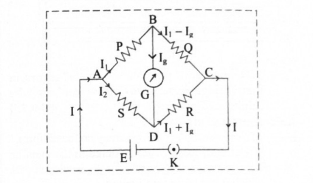
- 2Conversion of a galvanometer into a voltmeter RepeatsExplain how a moving coil galvanometer can be converted into a voltmeter. Derive the necessary formula.
Asked in: March 2008; March 2017
Show the derivationHide the derivation
Step 1To use a M.C.G as a voltmeter, a high resistance is connected in series with the M.C.G.Step 2A very high resistance X is connected in series with the galvanometer for this purpose as shown in figure.Step 3If V is the voltage to be measured, thenwhere is the current flowing through the galvanometer.Step 4If voltage V is times voltage (voltage across galvanometer) then,Using this in equation (1),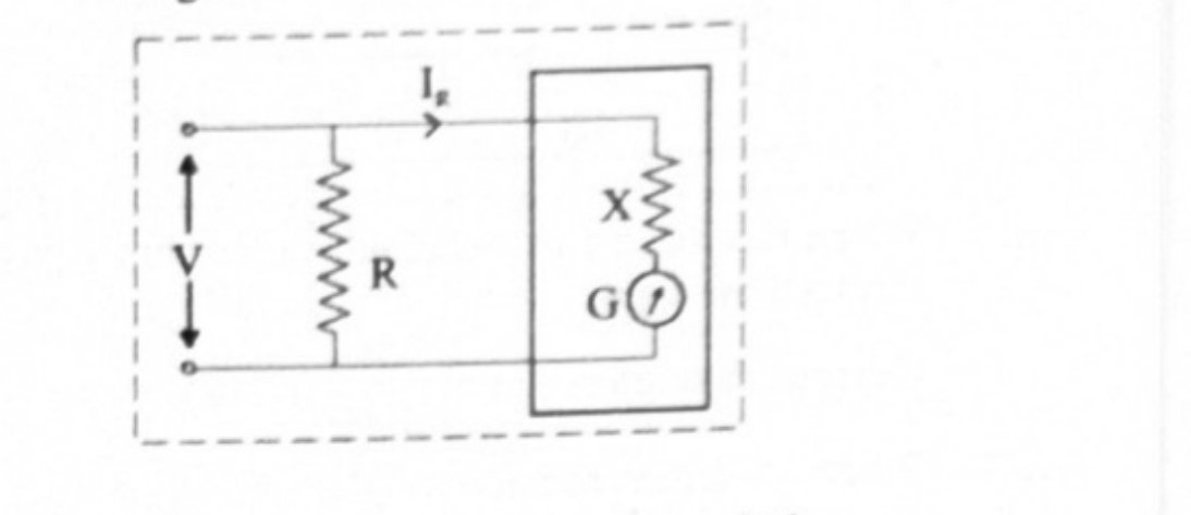
Finished revising this chapter? Practise Current Electricity →