9.3
Wheatstone Bridge
Current Electricity · Maharashtra HSC
Theory
Why the bridge exists
- The resistance of a material changes with temperature, strain, humidity, displacement, liquid level and so on, so any of these can be measured by measuring a resistance.
- Measurable resistances range from a few milliohm to hundreds of megohm, and different ranges need different methods. Wheatstone's bridge is generally used for resistances in the range from tens of ohm to hundreds of ohms.
- It was developed by Charles Wheatstone (1802-1875) to measure unknown resistances, and is also used for calibrating measuring instruments such as voltmeters and ammeters.
Balancing condition of Wheatstone's network
Construction
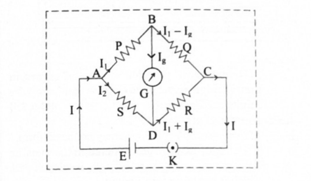
- Four resistances , , and are connected to form a quadrilateral ABCD.
- A battery of emf along with a key is connected between the points A and C, such that point A is at higher potential with respect to point C.
- A galvanometer of internal resistance is connected between the points B and D.
The diagram in words (Fig. 9.4)
- Draw the quadrilateral as a diamond. lies in arm AB, in arm BC, in arm CD and in arm DA. The cell with its key bridges the diagonal A to C; the galvanometer bridges the other diagonal, B to D. Current enters at A and leaves at C.
Working
- When the key is closed, current flows through the circuit. It divides into and at point A, where is the current through and the current through .
- The current gets divided at point B. Let be the current flowing through the galvanometer. The currents flowing through and are then and respectively.
- Consider the loop ABDA and apply Kirchhoff's voltage law in the clockwise sense:
- Now consider the loop BCDB and apply Kirchhoff's voltage law in the clockwise sense:
Balance
- A special case occurs when the current through the galvanometer is zero. The bridge is then said to be balanced, and the condition for balance is . It is obtained by adjusting the values of , , and .
- Substituting in equation (2):
- Substituting in equation (3):
- Dividing equation (4) by equation (5):
- This is the condition for balancing the Wheatstone bridge. Equivalently — the products of the opposite arms are equal. If any three resistances are known, the fourth can be determined.
- Note also that equations (1), (2) and (3) together, without assuming balance, let you find the current in any branch of the unbalanced bridge.
9.3.1 Metre bridge
Construction
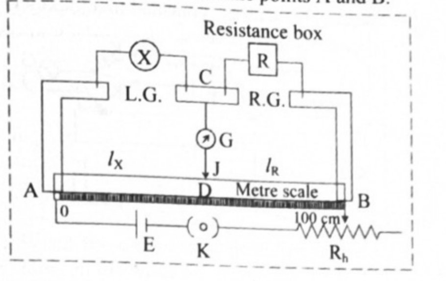
- A metre bridge consists of a wire of uniform cross section, one metre in length, stretched on a metre scale fixed on a wooden table.
- The ends of the wire are fixed below two L-shaped metallic strips. A single metallic strip separates the two L-shaped strips, leaving two gaps, the left gap and the right gap.
- Usually an unknown resistance is connected in the left gap and a resistance box is connected in the right gap.
- One terminal of a galvanometer is connected to the central strip at C, while the other terminal carries the jockey (J). Temporary contact with the wire AB is made with the jockey.
- A cell of emf along with a key and a rheostat is connected between the points A and B.
The diagram in words (Fig. 9.5)
- A horizontal one-metre wire AB laid along a metre scale. Above it, three thick metallic strips: two L-shaped end strips and one central strip, leaving two gaps in which (left) and the resistance box (right) are inserted. The galvanometer runs from the central strip C down to the jockey J, which touches the wire at D. Below the wire, the cell, key and rheostat complete the circuit from A to B.
Working
- A suitable resistance is selected from the resistance box.
- The jockey is brought into contact with AB at various points, and the balance point (null point) D is obtained — the galvanometer shows no deflection when the jockey is at D.
- Let the lengths of wire between A and D, and between D and B, be and .
- Using the balancing condition,
- where and are the resistances of the parts AD and DB of the wire.
- If is the specific resistance of the wire and its area of cross section,
- From equations (1), (2) and (3),
- Knowing , and , the unknown resistance can be determined. Since the wire is one metre long, cm.
Kelvin's method to determine the resistance of a galvanometer
Working
- The galvanometer whose resistance is to be determined is connected in one gap of the metre bridge, and a known resistance is connected in the other gap.
- A suitable resistance is taken in the resistance box. The current is sent round the circuit by closing the key. Without touching the jockey at any point of the wire, the deflection in the galvanometer is observed.
- The rheostat is adjusted to get a suitable deflection, around two thirds of the range.
- The jockey is then tapped at different points of the wire and a point of contact D is found for which the galvanometer shows no change in the deflection.
- Since the galvanometer shows the same deflection with or without contact between the points B and D, these two points must be equipotential points — the bridge is balanced.
- The length of the bridge wire between the point D and the left end of the wire is measured. Let be the length of the segment of wire opposite to the galvanometer and the length of the segment opposite to the resistance box.
Calculation
- Let and be the resistances of the two parts AD and DC of the bridge wire. Since the bridge is balanced,
- But , since for a uniform wire.
- Using this formula the unknown resistance of the galvanometer can be calculated.
- Note the contrast with the ordinary metre bridge: here balance is a no-change in deflection, not a zero deflection, because the galvanometer is itself one arm of the bridge rather than the detector in the central branch.
Sources of error and how they are minimised
- Sources of errors: (i) the cross section of the wire may not be uniform; (ii) the ends of the wire are soldered to the metallic strips, where contact resistance develops which is not taken into account; (iii) the measurements of and may not be accurate.
- To minimise them: (i) the value of is adjusted so that the null point is obtained around the middle one third of the wire, between 34 cm and 66 cm, so that the percentage errors in the measurement of and are minimum and nearly the same; (ii) the experiment is repeated by interchanging the positions of the unknown resistance and the known resistance box ; (iii) the jockey should be tapped on the wire and not slided, because the jockey is used only to detect whether there is a current through the central branch, and this is possible only by tapping.
Applications of the Wheatstone bridge
- Measuring the values of very low resistances precisely.
- Measuring quantities such as galvanometer resistance, capacitance, inductance and impedance.
- With an operational amplifier, measuring physical parameters such as temperature and strain.
Post office box
- A post office box is a practical form of Wheatstone bridge. It consists of three arms , and whose resistances are adjustable.
- The two ratio arms and contain resistances of 10 ohm, 100 ohm and 1000 ohm each. The third arm contains resistances from 1 ohm to 5000 ohm. The unknown resistance , usually in the form of a wire, forms the fourth arm. There are two tap keys and .
- The resistances in and are fixed to the desired ratio, and is adjusted until the galvanometer shows no deflection. The bridge is then balanced and
- If is the length and the radius of the wire , its specific resistance is
Wheatstone bridge for strain measurement
- Strain gauges are used to measure strain; their electrical resistance is proportional to the strain in the device, and in practice their resistance ranges from 30 ohm to 3000 ohm. For a given strain the resistance change may be only a fraction of the full range, so a Wheatstone bridge configuration is used to measure such small changes accurately.
- The unknown resistor of the bridge is replaced by the strain gauge. Two resistors and are equal to each other and is a variable resistor.
- With no force applied to the gauge, the rheostat is varied until the voltmeter indicates zero deflection — the bridge is balanced, and the strain at this condition represents the zero of the gauge.
- If the gauge is stretched or compressed its resistance changes, unbalancing the bridge and producing a voltage on the voltmeter which corresponds to the strain change. More strain gives a larger voltage difference across the meter terminals; zero strain gives a balanced bridge and a zero reading.
Standard results collected
- Balance: , i.e. .
- Metre bridge: with cm.
- Kelvin's method: .
- Post office box: , and .
- A ring or bangle joined to a gap at two diametrically opposite points contributes two halves in parallel, so its effective resistance is .
- To balance a bridge whose fourth arm is too large, shunt that arm: for arms 10, 10, 10 and 15 ohm, the 15 ohm arm must be brought to 10 ohm, and gives .
- If both gap resistances are changed, recompute from and compare with the old null point to get the shift and its direction.
Theory Questions Asked on This Subtopic
Real board questions. Answers are at the end of the page.
- 1
Obtain the balancing condition of Wheatstone's network.
 Maharashtra HSC board question — asked in October 2008Answer 1 ↓
 - 2
Draw a neat labelled circuit diagram to determine resistance of a galvanometer using Kelvin's method.
 Maharashtra HSC board question — asked in October 2008Answer 2 ↓
 - 3
State any 'two' possible sources of errors in metrebridge experiment. How can they be minimised?
Maharashtra HSC board question — asked in October 2015Answer 3 ↓ - 4
Describe meterbridge experiment to determine resistance of galvanometer by Kelvin. OR Describe Kelvin's method to determine the resistance of a galvanometer by using a metrebridge.
Maharashtra HSC board question — asked in March 2009; March 2016Answer 4 ↓ - 5
Explain with neat circuit diagram, how will you determine the unknown resistance 'X' by using a metrebridge experiment.
 Maharashtra HSC board question — asked in March 2018Answer 5 ↓
 - 6
State Kirchhoff's second law for a closed circuit. How will you minimize the errors in Kelvin's method?
Maharashtra HSC board question — asked in July 2019Answer 6 ↓
Numericals
Every numerical set on this subtopic. Full working is at the end of the page.
- 7
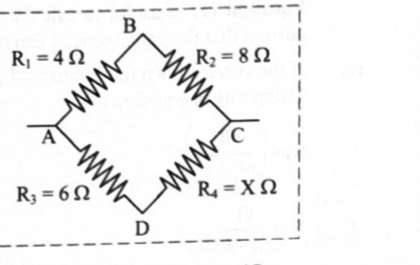
[Oct 13] Four resistances 4 Ω, 8 Ω, X Ω and 6 Ω are connected in a series so as to form Wheatstone's network. If the network is balanced, find the value of 'X'.
 Maharashtra HSC board questionAnswer 7 ↓
 - 8
[Mar 14] Two diametrically opposite points of a metal ring are connected to two terminals of the left gap of metrebridge. The resistance of 11 Ω is connected in right gap. If null point is obtained at a distance of 45 cm from the left end, find the resistance of metal ring.
Maharashtra HSC board questionAnswer 8 ↓ - 9
[Mar 17] An unknown resistance is placed in the left gap and resistance of 50 ohm is placed in the right gap of a metrebridge. The null point is obtained at 40 cm from the left end. Determine the unknown resistance.
Maharashtra HSC board questionAnswer 9 ↓ - 10
[Feb 20] Two resistances X and Y in the two gaps of a metrebridge gives a null point dividing the wire in the ratio 2:3. If each resistance is increased by 30 Ω, the null point divides the wire in the ratio 5:6, calculate the value of X and Y.
Maharashtra HSC board questionAnswer 10 ↓ - 11
[July 23] With an unknown resistance X in the left gap and a resistance of 30 Ω in the right gap of a meter-bridge, the null point is obtained at 40 cm from the left end of the wire. Calculate the unknown resistance and shift in the position of the null point, when resistance in each gap is increased by 15 Ω.
Maharashtra HSC board questionAnswer 11 ↓
Answers & Solutions
Work the questions above first, then check yourself here. Each answer is set out the way it should be written in the paper.
Construction: i. Four resistances P, Q, R and S are connected to form a quadrilateral ABCD as shown in the figure. ii. A battery of emf E along with a key is connected between the points A and C such that point A is at higher potential with respect to the point C. iii. A galvanometer of internal resistance G is connected between points B and D. Working: i. When the key is closed, current I flow through the circuit. It divides into and at point A. is the current through P and is the current through S. ii. The current gets divided at point B. Let be the current flowing through the galvanometer. The currents flowing through Q and R are and respectively. iii. Consider the loop ABDA, applying Kirchhoff's voltage law in the clockwise sense shown in the loop. iv. Now consider loop BCDB, applying Kirchhoff's voltage law in the clockwise sense as shown in the loop, v. The bridge is said to be balanced, when the current passing through the galvanometer is zero, i.e., . This condition can be obtained by adjusting the values of P, Q, R and S. vi. Substituting in equation (1), Substituting in equation (2), Dividing equation (3) by equation (4), This is the balancing condition for Wheatstone bridge.
The question is a real board question. Its answer and working are ours — this paper was published without an official answer key.
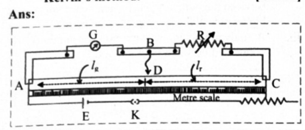
Circuit diagram — Kelvin's method
- The connections are made as shown, the galvanometer G occupying the left gap and the resistance box R the right gap of the metre bridge.
Labels on the diagram
Symbol What it is AC One metre wire of uniform cross section, stretched along a metre scale G The galvanometer whose resistance is to be found, connected in the left gap R Known resistance box, connected in the right gap B The central metallic strip, joined by a plain wire to the jockey J Jockey, tapped (never slided) on the wire D Balance point — the deflection does not change when the jockey touches it Length AD, the segment of wire opposite to the galvanometer Length DC, the segment of wire opposite to the resistance box E, K, Rh Cell, key and rheostat in the primary circuit across A and C How balance is recognised
- i. Note that the galvanometer here is one arm of the Wheatstone network, not the detector in the central branch.
- ii. The key is closed and the deflection is noted without touching the jockey; the rheostat is adjusted to bring it to about two thirds of the range.
- iii. The jockey is tapped at different points until a point D is found for which the deflection shows no change on making contact. Since the deflection is the same with and without contact, B and D are at the same potential and the bridge is balanced.
Result
Sources of errors: i. The cross section of the wire may not be uniform. ii. The ends of the wire are soldered to the metallic strip where contact resistance is developed, which is not taken into account. iii. The measurements of and may not be accurate. To minimize the errors i. The value of R is so adjusted that the null point is obtained around middle one third of the wire (between 34 cm and 66 cm) so that percentage error in the measurement of and are minimum and nearly the same. ii. The experiment is repeated by interchanging the positions of unknown resistance X and known resistance box R. iii. The jockey should be tapped on the wire and not slided. The jockey is used to detect whether there is a current through the central branch. This is possible only by tapping the jockey. [Any two sources of errors and their minimization]
Refer Subtopic 9.3: Q. No. 2 for diagram Working: i. The galvanometer whose resistance (G) is to be determined is connected in one gap and a known resistance (R) in the other gap. ii. A suitable resistance is taken in the resistance box. The current is sent round the circuit by closing the key. Without touching the jockey at any point of the wire, the deflection in the galvanometer is observed. iii. The rheostat is adjusted to get a suitable deflection around of range. iv. Now, the jockey is tapped at different points of the wire and a point of contact D for which, the galvanometer shows no change in the deflection, is found. v. As the galvanometer shows the same deflection with or without contact between the point B and D, these two points must be equipotential points. vi. The length of the bridge wire between the point D and the left end of the wire is measured. Let be the length of the segment of wire opposite to the galvanometer and be the length of the segment opposite to the resistance box. Calculation: i. Let and be the resistance of the two parts of the wire AD and DC respectively. ii. Since bridge is balanced, But, Using this formula, the unknown resistance of the galvanometer can be calculated.
Construction: i. Metrebridge consists of a one metre long wire of uniform cross section, stretched on a metre scale which is fixed on a wooden table. ii. The ends of the wire are fixed below two L shaped metallic strips. A single metallic strip separates the two L shaped strips leaving two gaps, left gap and right gap. iii. Usually, an unknown resistance X is connected in the left gap and a resistance box is connected in the other gap. iv. One terminal of a galvanometer is connected to the point C on the central strip, while the other terminal of the galvanometer carries the jockey (J). Temporary contact with the wire AB can be established with the help of the jockey. v. A cell of emf E along with a key and a rheostat are connected between the points A and B. Working: i. A suitable resistance R is selected from resistance box. ii. The jockey is brought in contact with AB at various points on the wire AB and the balance point (null point), D is obtained. The galvanometer shows no deflection when the jockey is at the balance point (point D). iii. Let the respective lengths of the wire between A and D, and that between D and B be and . iv. Then using the balancing conditions, where and are resistance of the parts AD and DB of the wire respectively. v. If and are lengths of the parts AD and DB of the wire AB, ρ is its specific resistance of the wire, and A is its area of cross section of wire AB then From equations (1), (2) and (3), Thus, knowing R, and , the value of the unknown resistance X can be determined.
i. Kirchhoff's second law for a closed circuit: Statement: The algebraic sum of the potential differences (products of current and resistance) and the electromotive forces (emfs) in a closed loop is zero. ii. Ways to minimize the errors: a. The value of R is so adjusted that the null point is obtained around middle one third of the wire (between 34 cm and 66 cm) so that percentage error in the measurement of and are minimum and nearly the same. b. The experiment is repeated by interchanging the positions of unknown resistance X and known resistance box R. c. The jockey should be tapped on the wire and not slided. The jockey is used to detect whether there is a current through the central branch. This is possible only by tapping the jockey.
Given: , , . To find: Unknown resistance (X). Formula: Calculation: From formula, Ans: The unknown resistance is 12 Ω.
Given: , cm m, m To find: Resistance of metal ring () Formula: Calculation: Resistance of each half segment of the metal ring and these half segments are connected in parallel in the left gap. From the formula, Ans: The resistance of the metal ring is 36 Ω.
Given: R = 50 Ω, cm = 0.4 m, cm = 0.6 m To find: Unknown resistance (X) Formula: Calculation: From formula, Ans: The value of unknown resistance is 33.33 Ω.
Given: , To find: Resistance (X and Y) Formula: Calculation: From 1st condition, From 2nd condition, From equations (i) and (ii), we have, Ans: i. The value of resistance X is 20 Ω. ii. The value of resistance Y is 30 Ω.
Given: R = 30 Ω, cm, cm To find: i. The unknown resistance (X) ii. Shift in the position of the null point a. When the resistance is increased b. When the resistance is shunted Formula: Calculation: i. From formula, ii. When the resistance in both the gaps are increased by 15 Ω: Since, From formula (i), cm cm Shift in null point Shift in null point = 3.75 cm towards right Ans: Shift in null point is 3.75 cm towards right.