9.2
Kirchhoff's Laws of Electrical Network
Current Electricity · Maharashtra HSC
Theory
Terms defined before the laws
- Junction: any point in an electric circuit where two or more conductors are joined together.
- Loop (mesh): any closed conducting path in an electric network.
- Branch: any part of the network that lies between two junctions.
- In Fig. 9.1 there are two junctions, labelled a and b, and three branches — the three possible paths 1, 2 and 3 from a to b.
- The two laws below apply to a steady current flowing through an electrical network of resistors.
9.2.1 Kirchhoff's first law (current law, junction law)
Statement
- The algebraic sum of the currents at a junction in an electrical network is zero.
- where is the current in the conductor at a junction having conductors.
Sign convention
- The currents arriving at the junction are considered positive.
- The currents leaving the junction are considered negative.
The diagram in words (Fig. 9.2)
- A single point P at which six conductors meet. Three of the arrows (, , ) point inwards, towards P; three (, , ) point outwards, away from P.
Applying it
- Arriving currents , , are positive; leaving currents , , are negative. Rearranged,
- so the total current flowing towards the junction equals the total current flowing away from the junction.
Why it is true
- The junction law is consistent with the conservation of electric charge. Some charge is received per unit time due to the currents arriving at the junction; for charge to be conserved, the same amount of charge must leave the junction per unit time, since charge cannot accumulate at a point.
9.2.2 Kirchhoff's second law (voltage law, loop theorem)
Statement
- The algebraic sum of the potential differences (products of current and resistance) and the electromotive forces (emfs) in a closed loop is zero.
Sign convention
- While tracing a loop through a resistor, if we travel along the direction of the conventional current, the potential difference across that resistance is taken as negative. If the loop is traced against the direction of the conventional current, the potential difference across that resistor is taken as positive.
- The emf of an electrical source is positive while tracing the loop within the source from its negative terminal to its positive terminal. It is taken as negative while tracing within the source from the positive terminal to the negative terminal.
The diagram in words (Fig. 9.3)
- A two-loop network. The left loop ABFGA contains the source and resistances , carrying , with in the central branch carrying . The right loop BFDCB contains the source and resistances , carrying , sharing the same central branch .
Applying it
- Loop ABFGA traced clockwise:
- Loop BFDCB traced anticlockwise:
Why it is true
- The voltage law is consistent with the law of conservation of energy. The algebraic sum of the emfs is the electrical energy supplied per unit charge by the sources; by conservation of energy this energy must reappear as potential differences across the electrical elements in the loop.
Steps usually followed while solving a problem using Kirchhoff's laws
- Choose some direction for the currents.
- Reduce the number of variables using Kirchhoff's first law.
- Determine the number of independent loops.
- Apply the voltage law to all the independent loops.
- Solve the equations obtained simultaneously.
- If the answer for a current variable is negative, the conventional current flows in the direction opposite to the one chosen.
Worked pattern: two cells in parallel across a resistance
- Standard question: two batteries of emfs , with internal resistances , are connected in parallel across an external resistance , sending current in the same direction through .
- Let and be the currents through the two cells; the current through is .
- Loop through cell 1 and : .
- Loop through cell 2 and : .
- Solve the pair simultaneously; the potential difference across is .
- For V, , V, , , this gives a current through the external resistance of A. A negative value for one of , simply means that cell is being driven backwards by the other.
Standard results collected
- at a junction; charge conservation.
- round a loop; energy conservation.
- and for a single cell driving a single resistance; a voltmeter of resistance across such a cell reads , always less than .
- Kirchhoff's laws are applicable to both DC and AC circuits; for AC, instantaneous values of currents and voltages are used.
Theory Questions Asked on This Subtopic
Real board questions. Answers are at the end of the page.
- 1
State Kirchhoff's laws of electricity. OR State Kirchhoff's laws of electrical network.
Maharashtra HSC board question — asked in July 2018; July 2022; March 2010Answer 1 ↓
Numericals
Every numerical set on this subtopic. Full working is at the end of the page.
- 2
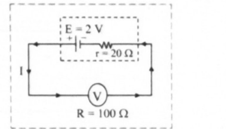
[July 16] A voltmeter has a resistance of 100 Ω. What will be its reading when it is connected across a cell of e.m.f. 2 V and internal resistance 20 Ω?
 Maharashtra HSC board questionAnswer 2 ↓
 - 3
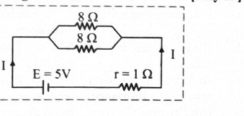
[July 19] Find the total current 'I' flowing through the following circuit:
 Maharashtra HSC board questionAnswer 3 ↓
 - 4
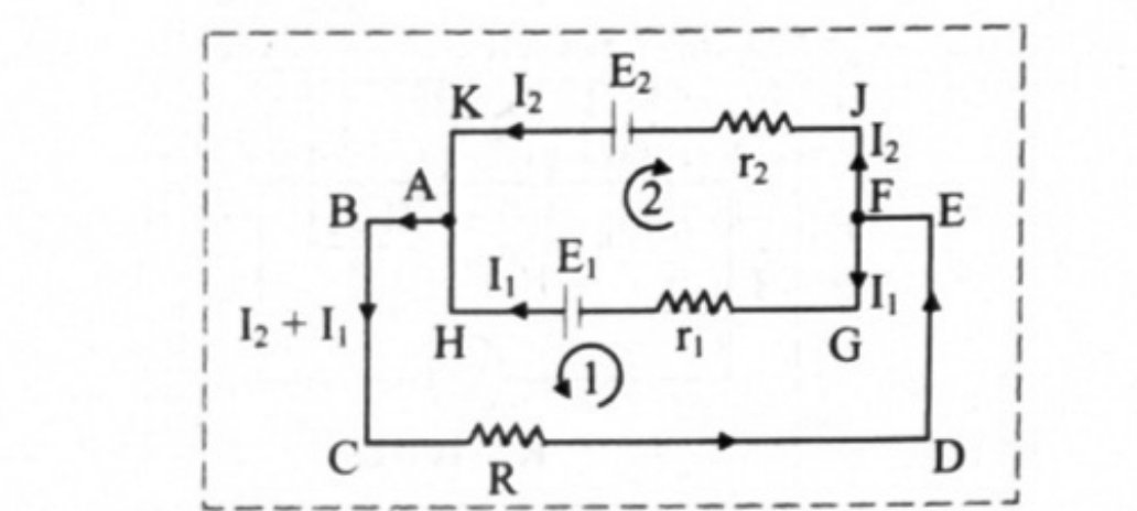
[Mar 22] Two cells of emf 4 V and 2 V having respective internal resistance of 1 Ω and 2 Ω are connected in parallel, so as to send current in the same direction through an external resistance of 5 Ω. Find the current through the external resistance.
 Maharashtra HSC board questionAnswer 4 ↓
Answers & Solutions
Work the questions above first, then check yourself here. Each answer is set out the way it should be written in the paper.
i. Kirchhoff's first law (Current law or junction law): Statement: The algebraic sum of the currents at a junction is zero in an electrical network. where is the current in the conductor at a junction having n conductors. ii. Kirchhoff's second law (Voltage law or loop theorem): Statement: The algebraic sum of the potential differences (products of current and resistance) and the electromotive forces (emfs) in a closed loop is zero.
Given: R = 100 Ω, r = 20 Ω, E = 2 V To find: Reading of voltmeter (V) Formula: V = E − Ir Calculation: Current through the circuit is given by From formula, V Ans: The reading on the voltmeter is 1.667 V.
From figure, two 8 Ω resistors are connected in parallel. Total resistance in that branch is, this combination is connected in series with 1 Ω. Ans: The total current 'I' flowing through the circuit is 1 A.
Given: V, , V, , R = 5 Ω Applying Kirchhoff's 2nd law in Loop 1 (ABCDEFGHA), Applying Kirchhoff's 2nd law in Loop 2 (FGHAKJF), Substituting equation (ii) in equation (i), Current through external resistance 'R' A Ans: Current through external resistance is 10/17 A.