9.4
Potentiometer
Current Electricity · Maharashtra HSC
Theory
Why a potentiometer and not a voltmeter
- A voltmeter measures the potential difference between two points in a circuit. An ideal voltmeter, which does not change the potential difference being measured, should have infinite resistance so that it draws no current. Practically, no voltmeter can be built with infinite resistance.
- A potentiometer draws no current from the circuit under test at balance, so it behaves as an ideal voltmeter. It is used for the accurate measurement of potential difference and of emf.
9.4.1 Principle of the potentiometer
Statement of the principle
- The potential difference between two points on the wire is directly proportional to the length of the wire between them, provided the wire is of uniform cross section, the current through the wire is the same, and the temperature of the wire remains constant.
The diagram in words (Fig. 9.6)
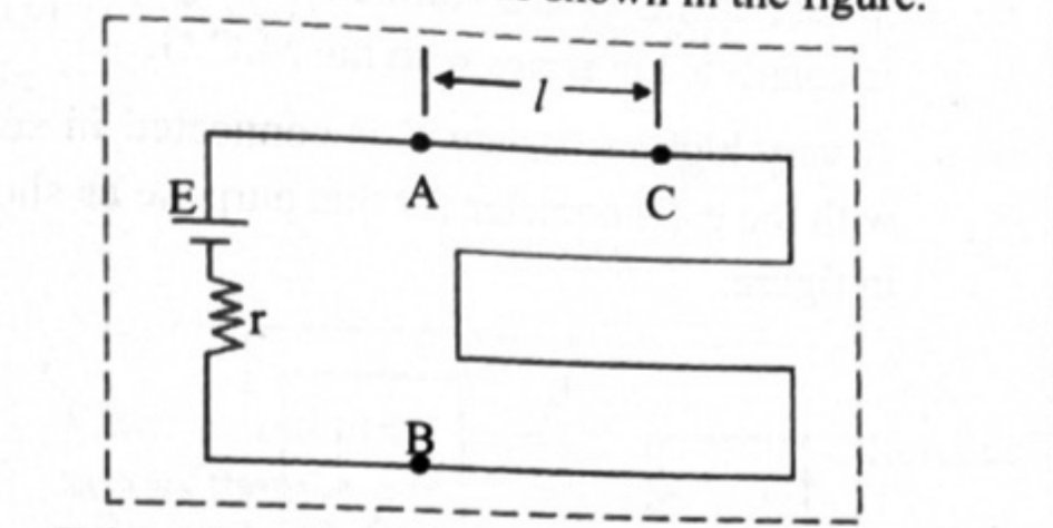
- A long straight wire AB of length stretched along a scale. A cell of emf with internal resistance , a key and (in practice) a rheostat are connected across A and B, so that a steady current flows from A to B and A is at the higher potential. A point C is marked on the wire at a distance from A.
Derivation
- A potentiometer consists of a long wire AB of length and resistance , having uniform cross sectional area . A cell of emf with internal resistance is connected across AB. When the circuit is switched on, a current passes through the wire.
- The potential difference across AB is , so from equation (1),
- Therefore the potential difference per unit length of the wire is
- As long as remains constant, remains constant. It is known as the potential gradient along AB and is denoted by .
- Potential gradient is defined as the potential difference per unit length of wire. Its SI unit is (often quoted in in numericals).
- Consider a point C on the wire at distance from A. If the potential difference between A and C is , then
- Thus the potential difference between two points on the wire is directly proportional to the length of wire between them, provided (a) the wire is of uniform cross section, (b) the current through the wire is the same, and (c) the temperature of the wire remains constant.
Notes on the potential gradient
- Written through the current, , where is the resistance per unit length of the wire.
- With an extra resistance (rheostat or resistance box) in series in the primary circuit, — this is the form used whenever a question asks what series resistance gives a desired potential drop per centimetre.
- therefore depends on the emf of the auxiliary cell, the resistance and length of the potentiometer wire, and the internal and series resistances in the primary circuit — equivalently on the current through the wire and its resistance per unit length. It does not depend at all on the cell being tested.
- Measuring : balance a cell of known emf and measure its balancing length ; then .
- Numerically the potential gradient along the wire equals the magnitude of the electric field along it, , in .
9.4.2 Uses of a potentiometer
A) To compare the emfs of two cells — Method I, cells connected individually
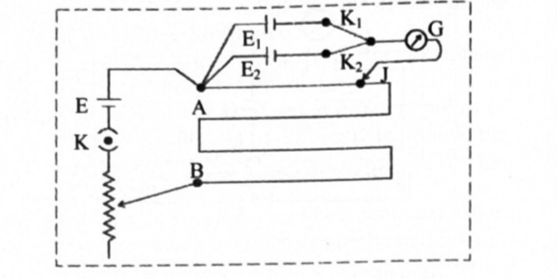
- A potentiometer circuit is set up by connecting a battery of emf , with a key K and a rheostat, such that point A is at a higher potential than point B.
- The cells whose emfs are to be compared are connected with their positive terminals at point A and their negative terminals to the extreme terminals of a two-way key .
- The central terminal of the two-way key is connected to a galvanometer, and the other end of the galvanometer is connected to a jockey J.
- Diagram in words (Fig. 9.7): the primary circuit — cell , key K, rheostat — across the wire AB. The secondary circuit branches from A, passes through the two cells and on the two arms of the two-way key, and returns through the galvanometer to the jockey resting on the wire.
- Key K is closed, then key is closed and kept open, so the cell of emf comes into the circuit. The null point is obtained by touching the jockey at various points on AB. Let be the length of wire between the null point and A; corresponds to .
- where is the potential gradient along the potentiometer wire.
- Now is kept open and is closed, so the cell of emf comes into the circuit. The null point is again obtained; let be the corresponding length from A.
- Dividing equation (1) by equation (2),
- Thus the emfs of the two cells can be compared, and if one of them is known the other can be determined.
A) Method II — sum and difference (combination) method
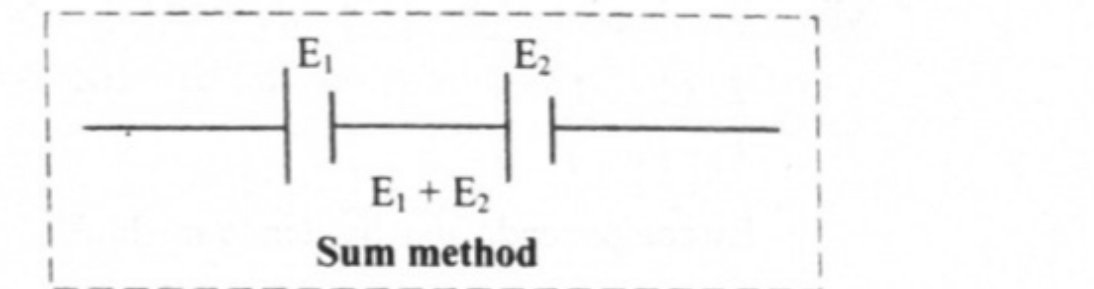
- When two cells are connected so that the negative terminal of the first cell is joined to the positive terminal of the second, their emfs add and the effective emf of the combination is . This is the sum method.
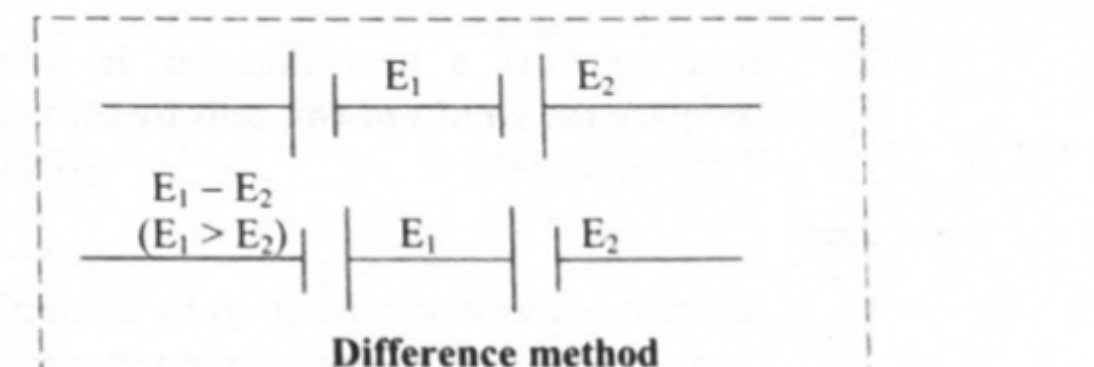
- When two cells are connected so that their negative terminals are together, or their positive terminals are together, their emfs oppose each other and the effective emf is (taking ). This is the difference method. Note that this is not a parallel combination of cells.
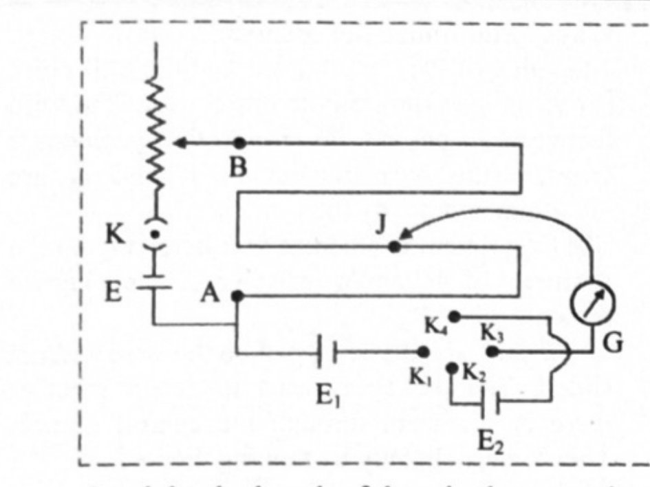
- Diagram in words (Fig. 9.9): the primary circuit as before across AB. The two cells are wired through four keys , , , so that closing and puts them in the sum mode and closing and puts them in the difference mode; the galvanometer and jockey form the detector as before.
- With and closed the cells are in the sum mode. The null point is obtained; let be the length between the null point and A. This corresponds to .
- Now and are opened and and are closed, putting the cells in the difference mode. The null point is obtained again; let be the corresponding length. This corresponds to .
- Dividing equation (1) by equation (2),
- By componendo and dividendo,
- Thus the emfs of the two cells can be compared by the sum and difference method.
B) To find the internal resistance of a cell
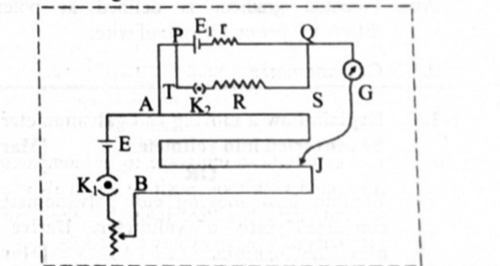
- The set-up consists of a potentiometer wire AB connected in series with a cell of emf , a key and a rheostat; terminal A is at a higher potential than B.
- The cell of emf whose internal resistance is to be determined is connected to the potentiometer wire through a galvanometer G and the jockey J. A resistance box is connected across the cell through a key .
- Diagram in words (Fig. 9.10): primary circuit — cell , key , rheostat — across AB. Secondary circuit — from A through the cell , then the galvanometer, then the jockey on the wire; the resistance box with key sits directly across the terminals of . The loop PQSTP referred to in the derivation is the loop containing and .
- The key is closed and is open. The circuit then consists of the cell , the cell and the potentiometer wire, and no current is drawn from at the null point, so the balancing length corresponds to the full emf . Let be that length from A.
- where is the potential gradient of the potentiometer wire, which is constant.
- Now both and are closed, so the circuit consists of the cell , the cell , the resistance box, the galvanometer and the jockey. Some resistance is selected from the box and the null point is obtained. The length between the null point and A is measured; it corresponds to the terminal potential difference across the cell.
- Dividing equation (1) by equation (2),
- Consider the loop PQSTP: and . Therefore
- This equation gives the internal resistance of the cell. Note that always, since the terminal p.d. is less than the emf.
- The internal resistance of a cell itself depends on the nature of the electrolyte, the concentration of the electrolyte, the distance between the electrodes, the area of the electrodes immersed in the electrolyte, and the temperature.
C) Practical applications of the potentiometer
- Voltage divider: a potential is set up between A and B of the potentiometer wire; one end of a device is connected to the positive point A and the other to a slider that moves along AB. The voltage then divides in proportion to the lengths and on either side of the slider, giving a continuously variable output voltage from a fixed supply.
- Audio control: sliding potentiometers (faders) and rotary potentiometers (knobs) are used in modern low-power audio systems for frequency attenuation, loudness control and for controlling other characteristics of audio signals.
- Potentiometer as a sensor: if the slider is connected to the moving part of a machine, the potentiometer works as a motion sensor. A small displacement of the moving part changes the potential, which is amplified, and the potential difference is calibrated in terms of the displacement.
9.4.3 Advantages of a potentiometer over a voltmeter
Merits
- A potentiometer is more sensitive than a voltmeter.
- A potentiometer can be used to measure a potential difference as well as the emf of a cell. A voltmeter always measures terminal potential difference and, since it draws some current, cannot be used to measure the emf of a cell.
- Measurement of potential difference or emf is very accurate with a potentiometer. A very small potential difference of the order of volt can be measured with it, and its least count is much better than that of a voltmeter.
- For all these reasons a potentiometer is preferred over a voltmeter for measuring emf.
Demerits
- A potentiometer is not portable.
- Direct measurement of potential difference or emf is not possible with it — every result is obtained indirectly, from a balancing length.
Distinguishing potentiometer from voltmeter
| Potentiometer | Voltmeter |
|---|---|
| Its resistance is infinite | Its resistance is high but finite |
| It does not draw any current from the source of known emf | It draws some current from the source of emf |
| The potential difference measured by it is equal to the actual potential difference | The potential difference measured by it is less than the actual potential difference |
| It has high sensitivity | It has low sensitivity |
| It measures emf as well as p.d. | It measures only p.d. |
| It is used to measure the internal resistance of a cell | It cannot be used to measure the internal resistance of a cell |
| It is more accurate | It is less accurate |
| It does not give a direct reading | It gives a direct reading |
| It is not portable | It is portable |
| It is used to measure lower voltage values only | It is used to measure lower as well as higher voltage values |
Standard results collected
- , with a series resistance giving .
- ; at the null point.
- (individual cells) and (sum and difference).
- , with the equivalent form .
- At the balance point no current flows through the galvanometer branch, so current is drawn from the auxiliary battery only, not from the cell under test.
- Increasing the current through the potentiometer wire increases and so shortens the balancing length, shifting the null point towards A; decreasing the current lengthens it, shifting the null point towards B. If becomes smaller than no null point can be found on the wire at all.
- The jockey must be tapped, not slid: sliding scrapes the wire and destroys the uniformity of its cross section, and the jockey is needed only to detect whether current flows.
Theory Questions Asked on This Subtopic
Real board questions. Answers are at the end of the page.
- 1
Describe how a potentiometer is used to compare the emfs of two cells by combination method.
 Maharashtra HSC board question — asked in March 2008Answer 1 ↓
 - 2
Describe how a potentiometer is used to compare the e.m.f.s of two cells by connecting them separately.
 Maharashtra HSC board question — asked in October 2009Answer 2 ↓
 - 3
State and explain principle of potentiometer.
 Maharashtra HSC board question — asked in October 2013Answer 3 ↓
 - 4
State the advantages of potentiometer over voltmeter.
Maharashtra HSC board question — asked in March 2017Answer 4 ↓ - 5
Distinguish between potentiometer and voltmeter.
Maharashtra HSC board question — asked in March 2022Answer 5 ↓ - 6
State the formula giving relation between electric field intensity and potential gradient.
Maharashtra HSC board question — asked in February 2023Answer 6 ↓ - 7
Explain the use of potentiometer to determine internal resistance of a cell.
 Maharashtra HSC board question — asked in February 2023Answer 7 ↓
 - 8
Define potential gradient of the potentiometer wire. OR Define potential gradient.
Maharashtra HSC board question — asked in July 2023; March 2022Answer 8 ↓
Numericals
Every numerical set on this subtopic. Full working is at the end of the page.
- 9
[Mar 10] The potentiometer wire has length 10 m and resistance 10 Ω. If the current flowing through it is 0.4 A, what are the balancing lengths when two cells of e.m.fs 1.3 V and 1.1 V are connected so as to i. assist and ii. oppose each other?
Maharashtra HSC board questionAnswer 9 ↓ - 10
[Mar 13] A cell balances against a length of 200 cm on a potentiometer wire when it is shunted by a resistance of 8 Ω. The balancing length reduces by 40 cm when it is shunted by a resistance of 4 Ω. Calculate the balancing length when the cell is in open circuit. Also calculate the internal resistance of the cell.
Maharashtra HSC board questionAnswer 10 ↓ - 11
[Oct 14] A potentiometer wire has a length of 4 m and a resistance of 5 Ω. What resistance should be connected in series with a potentiometer wire and a cell of e.m.f. 2V having internal resistance 1 Ω to get a potential gradient of V/cm?
Maharashtra HSC board questionAnswer 11 ↓ - 12
[Mar 15] Resistance of a potentiometer wire is 0.1 Ω/cm. A cell of e.m.f. 1.5 V is balanced at 300 cm on this potentiometer wire. Calculate the current and balancing length for another cell of e.m.f. 1.4 V on the same potentiometer wire.
Maharashtra HSC board questionAnswer 12 ↓ - 13
[Mar 09, Oct 15] A potentiometer wire has a resistance per unit length of 0.1 Ω/m. A cell of e.m.f. 1.5 V balances against 300 cm length of the wire. Find the current through potentiometer wire.
Maharashtra HSC board questionAnswer 13 ↓ - 14
[July 16] A potentiometer wire has a length of 2 m and resistance of 10 Ω. It is connected in series with resistance 990 Ω and a cell of e.m.f 2V. Calculate the potential gradient along the wire.
Maharashtra HSC board questionAnswer 14 ↓ - 15
[July 17] When a resistance of 12 ohm is connected across a cell, its terminal potential difference is balanced by 120 cm length of potentiometer wire. When the resistance of 18 ohm is connected across the same cell, the balancing length is 150 cm. Find the balancing length when the cell is in open circuit. Also calculate the internal resistance of the cell.
Maharashtra HSC board questionAnswer 15 ↓ - 16
[July 18] In a potentiometer the balancing length of the wire is found to be 2.5 m for a cell of e.m.f. 1.5 V. Find the balancing length of the wire for another cell of e.m.f. 1.2 V on the same potentiometer.
Maharashtra HSC board questionAnswer 16 ↓ - 17
[Mar 19] When a resistor of 5 Ω is connected across the cell, its terminal potential difference is balanced by 150 cm of potentiometer wire and when a resistance of 10 Ω is connected across the cell, the terminal potential difference is balanced by 175 cm of the same potentiometer wire. Find the balancing length when the cell is in open circuit and the internal resistance of the cell.
Maharashtra HSC board questionAnswer 17 ↓ - 18
[July 22] When two cells of emfs and are connected in series so as to assist each other, their balancing length on potentiometer wire is found to be 3.2 m. When two cells are connected in series so as to oppose each other, the balancing length is found to be 0.7 m. Compare the emfs of two cells.
Maharashtra HSC board questionAnswer 18 ↓
Answers & Solutions
Work the questions above first, then check yourself here. Each answer is set out the way it should be written in the paper.
i. The emfs of two cells can be compared using sum and difference method. ii. When two cells are connected such that the positive terminal of the first cell is connected to the negative terminal of the second cell, the emf of the two cells are added up and the effective emf of the combination of two cells is . This method of connecting two cells is called the sum method. iii. When two cells are connected such that their negative terminals are together or their positive terminals are connected together, then their emf oppose each other and effective emf of the combination of two cells is (Considering ). This method of connecting two cells is called the difference method. iv. Circuit for sum and difference method is connected as shown in below figure. When keys and are closed the cells and are in the sum mode. The null point is obtained using the jockey. v. Let be the length of the wire between the null point and the point A. This corresponds to the emf . where K is the potential gradient along the potentiometer wire. vi. Now the key and are kept open and keys and are closed. In this case the two cells are in the difference mode. vii. Again the null point is obtained. Let be the length of the wire between the null point and the point A. This corresponds to emf . viii. Dividing equation (1) by equation (2), By componendo and dividendo method, Thus, emf of two cells can be compared using sum and difference method.
i. A potentiometer circuit is set up by connecting a battery of emf E, with a key K and a rheostat such that point A is at higher potential than point B. ii. The cells whose emfs are to be compared are connected with their positive terminals at point A and negative terminals to the extreme terminals of a two way key and . iii. The central terminal of the two ways key is connected to a galvanometer. The other end of the galvanometer is connected to a jockey (J). iv. Key K is closed and then, key is closed and key is kept open. Therefore, the cell of emf comes into circuit. v. The null point is obtained by touching the jockey at various points on the potentiometer wire AB. vi. Let be the length of the wire between the null point and the point A. Here, corresponds to emf of the cell. Therefore, where K is the potential gradient along the potentiometer wire. vii. Now key is kept open and key is closed. The cell of emf now comes in the circuit. Again, the null point is obtained with the help of the Jockey. viii. Let be the length of the wire between the null point and point A. Here corresponds to the emf of the cell. ix. Dividing equation (1) by equation (2), Thus, emfs of the two cells can be compared and if any one of the emfs is known, the other can be determined.
Principle: The potential difference between two points on the wire is directly proportional to the length of the wire between them provided the wire is of uniform cross section, the current through the wire is the same and temperature of the wire remains constant. Explanation: i. A potentiometer consists of a long wire AB of length L and resistance R having uniform cross sectional area A. ii. A cell of emf E having internal resistance r is connected across AB as shown in the figure. iii. When the circuit is switched on, current I pass through the wire. Current through AB, iv. Potential difference across AB, v. Therefore, the potential difference per unit length of the wire is, As long as E remains constant, will remain constant. vi. is known as potential gradient along AB and is denoted by K. Potential gradient can be defined as potential difference per unit length of wire. vii. Consider a point C on the wire at distance from the point A, as shown in the figure. If the potential difference between A and C is , then, i.e., viii. Thus, the potential difference between two points on the wire is directly proportional to the length of the wire between the two points, provided (a) the wire is of uniform cross section, (b) the current through the wire is the same and (c) temperature of the wire remains constant.
i. Potentiometer is more sensitive than a voltmeter. ii. A potentiometer can be used to measure a potential difference as well as an emf of a cell. A voltmeter always measures terminal potential difference, and as it draws some current, it cannot be used to measure an emf of a cell. iii. Measurement of potential difference or emf is very accurate in the case of a potentiometer. A very small potential difference of the order volt can be measured with it. Least count of a potentiometer is much better compared to that of a voltmeter. Due to all these reasons potentiometer is preferred over a voltmeter for measuring emf.
No. Potentiometer Voltmeter i. Its resistance is infinite. Its resistance is high but finite. ii. It does not draw any current from the source of known e.m.f. It draws some current from the source of e.m.f. iii. The potential difference measured by it is equal to actual potential difference (p.d.). The potential difference measured by it is less than the actual potential difference (p.d.). iv. It has high sensitivity. It has low sensitivity. v. It measures e.m.f as well as p.d. It measures only p.d. vi. It is used to measure internal resistance of a cell. It cannot be used to measure the internal resistance of a cell. vii. It is more accurate. It is less accurate. viii. It does not give direct reading. It gives direct reading. ix. It is not portable. It is portable. x. It is used to measure lower voltage values only. It is used to measure lower as well as higher voltage values. [Any four differences]
Formula: Where, is the potential gradient and E is the electric field.
i. The experimental set up for this method consists of a potentiometer wire AB connected in series with a cell of emf E, the key , and rheostat as shown in figure. ii. The terminal A is at higher potential than terminal B. A cell of emf whose internal resistance r is to be determined is connected to the potentiometer wire through a galvanometer G and the jockey J. iii. A resistance box R is connected across the cell through the key . The key is closed and is open. iv. The circuit now consists of the cell E, cell , and the potentiometer wire. The null point is then obtained. v. Let be length of the potentiometer wire between the null point and the point A. This length corresponds to emf . where K is potential gradient of the potentiometer wire which is constant. vi. Now both the keys and are closed so that the circuit consists of the cell E, the cell , the resistance box, the galvanometer and the jockey. Some resistance R is selected from the resistance box and null point is obtained. vii. The length of the wire between the null point and point A is measured. This corresponds to the voltage between the null point and point A. Dividing equation (1) by equation (2), viii. Consider the loop PQSTP, and The above equation is used to determine the internal resistance of the cell.
Potential gradient is defined as potential difference per unit length of wire.
Given: L = 10 m, R = 10 Ω, I = 0.4 A, V, V To find: i. Null point distance when two cells assist each other () ii. Null point distance when two cells oppose each other () Formulae: i. ii. Calculation: i. Since, Here, r = 0 Ω When and are connected so as to assist then, From formula (i), m ii. From formula (ii), m Ans: i. The null point distance when two cells assist each other is 6 m. ii. The null point distance when two cells oppose each other is 0.5 m.
Given: , cm, , cm To find: Balancing length (), Internal resistance of the cell (r) Formula: Calculation: From first condition, From second condition, From equation (i) and (ii), cm Using equation (i) Internal resistance, Ans: i. The balancing length is 266.7 cm. ii. The internal resistance of the cell is 2.668 Ω.
Given: L = 4 m, , E = 2 V, r = 1 Ω, K = V/cm = V/m To find: Series resistance (X) Formula: Calculation: From formula, Ans: A resistance of 19 Ω should be connected in series.
Given: σ = 0.1 Ω/cm = 0.1×100 Ω/m = 10 Ω/m, cm = 3 m, V, V To find: Current (I), balancing length () Formulae: i. ii. Calculation: Using formula (i), Using formula (ii), Ans: i. The flow of current is 0.05 A. ii. The balancing length for second cell is 2.8 m.
Given: σ = 0.1 Ω/m, E = 1.5 V, L = 300 cm = 3 m To find: Current through potentiometer (I) Formulae: i. ii. Calculation: From formula (i), From formula (ii), A Ans: Current through the potentiometer wire is 5 A.
Given: L = 2 m, R = 10 Ω, , E = 2 V To find: Potential gradient of wire (K) Formula: Calculation: Since, Also, V = volt From formula, V/m Ans: The potential gradient of wire is V/m.
Given: , cm, , cm To find: Balancing length (), Internal resistance (r) Formula: Calculation: From first condition, From second condition, From equation (i) and (ii), cm Using equation (i) we get Internal resistance, Ans: i. The balancing length is 360 cm. ii. The internal resistance of the cell is 10 Ω.
Given: V, m, V To find: Balancing length of the wire () Formula: Calculation: From formula, Ans: The balancing length of the wire for another cell is 2 m.
Given: , cm, , cm To find: Balancing length (), Internal resistance (r) Formula: Calculation: From first condition, From second condition, From equation (i) and (ii), cm Using equation (i) we get Internal resistance, Ans: i. The balancing length is 300 cm. ii. The internal resistance of the cell is 18 Ω.
Given: m, m To find: Ratio of emfs of two cells Formula: Calculation: From formula, Ans: The ratio of emfs of two cells is 1.56.