9.5
Galvanometer
Current Electricity · Maharashtra HSC
Theory
What a galvanometer is
- A galvanometer is a device used to detect weak electric currents in a circuit.
- Its coil is pivoted (or suspended) between the concave pole faces of a strong laminated horseshoe magnet. When current passes through the coil, it deflects, and the deflection is proportional to the current.
- The deflection is read with a pointer attached to the coil; the position of the pointer on the scale indicates the current through the galvanometer or the potential difference across it.
- The coil has a moderate resistance, about 100 ohm, and the instrument has a small current carrying capacity, about 1 mA. With suitable modification it can therefore be used as an ammeter or as a voltmeter.
- Diagram in words (Fig. 9.12): a rectangular coil wound on a soft iron core, pivoted between the curved (concave) pole pieces N and S of a permanent horseshoe magnet, with a hair spring providing the restoring torque and a pointer sweeping a scale.
9.5.1 Galvanometer as an ammeter
What must change
- Let be the full-scale deflection current and the resistance of the coil of the moving coil galvanometer (MCG). To convert it into an ammeter — a current measuring instrument, always connected in series with the resistance through which the current is to be measured — three modifications are necessary.
- Its effective current capacity must be increased to the desired higher value.
- Its effective resistance must be decreased. The finite resistance , when connected in series, itself decreases the current through that is actually to be measured; in the ideal case an ammeter should have zero resistance.
- It must be protected from possible damage due to the passage of an excessive electric current.
The shunt
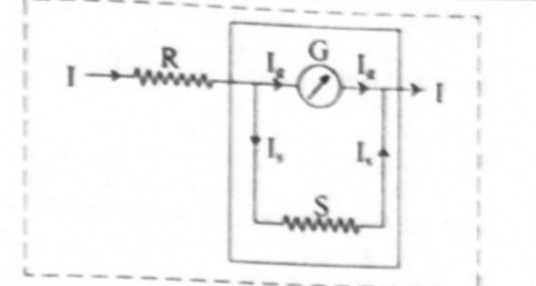
- In practice all three are achieved by connecting a low resistance in parallel with the galvanometer, which effectively reduces the resistance of the galvanometer. This low resistance connected in parallel is called a shunt, .
- Diagram in words (Fig. 9.13): the galvanometer coil G with the low resistance connected directly across its two terminals, the pair forming a single two-terminal ammeter placed in series in the main circuit. The main current enters, splits into through G and through S, and recombines.
- Uses of the shunt: it diverts a large part of the total current by providing an alternative path and thus protects the instrument from damage; it increases the range of the ammeter; it decreases the resistance between the points to which it is connected.
Derivation
- and are the currents through the circuit and through the galvanometer respectively, so the current through the shunt is
- Since and are in parallel, the potential difference across them is the same:
- Equation (1) is useful to calculate the range of current that the galvanometer can measure.
- If the current is times the current , then . Using this in equation (1),
- This is the required shunt to increase the range times.
- If is the current through the shunt, the remaining current flows through the galvanometer, so , i.e. , i.e. , giving
- This gives the fraction of the total current through the shunt resistance. Correspondingly .
- Resistance of the resulting ammeter: , which is small, as an ammeter's should be.
- If the only available shunt is too large to give the desired range, a resistance is added in series with the coil, so that the coil branch has resistance and .
9.5.2 Galvanometer as a voltmeter
What must change
- A voltmeter measures the potential difference between two points in an electrical circuit and is always connected in parallel with the component across which the voltage drop is to be measured. To convert an MCG into a voltmeter, three modifications are necessary.
- Its voltage measuring capacity must be increased to the desired higher value.
- Its effective resistance must be increased. If a galvanometer is used directly to measure voltage it draws some current, because of its low resistance, and so the actual potential difference to be measured decreases; a voltmeter should therefore have very high resistance, ideally infinite.
- It must be protected from possible damage due to an excess applied potential difference.
The series resistance
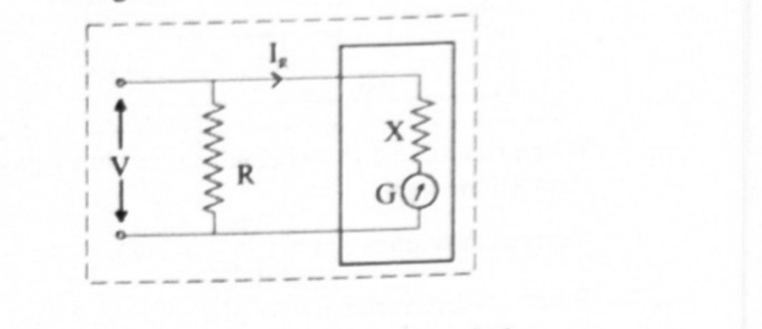
- All these requirements are fulfilled by connecting a resistance of suitable high value in series with the given MCG.
- Diagram in words (Fig. 9.14): the galvanometer coil G with the high resistance in series with it, the pair forming a single two-terminal voltmeter connected across the element whose p.d. is wanted.
Derivation
- If is the voltage to be measured, then
- where is the current flowing through the galvanometer at full-scale deflection.
- If the voltage is times the voltage across the galvanometer, then . Using this in equation (1),
- Resistance of the resulting voltmeter: , which is large, as a voltmeter's should be.
Comparison of an ammeter and a voltmeter
| Ammeter | Voltmeter |
|---|---|
| It measures current | It measures potential difference |
| It is connected in series | It is connected in parallel |
| It is an MCG with low resistance (ideally zero) | It is an MCG with high resistance (ideally infinite) |
| Smaller the shunt, greater will be the current measured | Larger its resistance, greater will be the potential difference measured |
| Resistance of ammeter, | Resistance of voltmeter, |
Thermoelectricity — Seebeck effect
- When electric current is passed through a resistor, electrical energy is converted into thermal energy. The reverse process, the direct conversion of thermal energy into electrical energy, was discovered by Seebeck, and the effect is called the thermoelectric effect.
- If two different metals are joined to form a closed circuit and the two junctions are kept at different temperatures, a small emf is produced and a current flows. This emf is called the thermo emf, the effect is the Seebeck effect, and the pair of dissimilar metals forming the junctions is called a thermocouple.
- For an antimony-bismuth thermocouple the current flows from antimony to bismuth at the cold junction (the ABC rule); for a copper-iron couple the current flows from copper to iron at the hot junction.
- The effect is reversible: the direction of the current reverses if the hot and cold junctions are interchanged.
- With the cold junction at and the hot junction at ,
- where and are the thermoelectric constants. The graph of thermo emf against temperature is therefore a parabola.
Standard results collected
- Shunt for an ammeter: ; for an -fold range, with .
- Current split: and .
- Series resistance for a voltmeter: with .
- Meter resistances: and .
- For an ideal voltmeter the resistance is infinite; for an ideal ammeter it is zero.
- If a shunt is already fitted and the combined resistance is known, recover the shunt from , i.e. .
- To extend the range of an existing voltmeter of resistance from to , connect in series, where .
Theory Questions Asked on This Subtopic
Real board questions. Answers are at the end of the page.
- 1
Explain how a moving coil galvanometer can be converted into voltmeter. OR Explain how moving coil galvanometer is converted into a voltmeter. Derive the necessary formula.
 Maharashtra HSC board question — asked in March 2008; March 2017Answer 1 ↓
 - 2
What is shunt?
Maharashtra HSC board question — asked in July 2022Answer 2 ↓ - 3
How will you convert a moving coil galvanometer into an ammeter?
 Maharashtra HSC board question — asked in February 2023Answer 3 ↓
 - 4
For a moving coil galvanometer, show that , where S is shunt resistance, G is galvanometer resistance, n is ratio of total current to the full scale deflection current.
Maharashtra HSC board question — asked in July 2023Answer 4 ↓ - 5
Distinguish between an ammeter and a voltmeter. (Two points each).
Maharashtra HSC board question — asked in February 2024Answer 5 ↓ - 6
What is the value of resistance for an ideal voltmeter? OR What is the resistance of an ideal voltmeter?
Maharashtra HSC board question — asked in February 2023; February 2024Answer 6 ↓
Numericals
Every numerical set on this subtopic. Full working is at the end of the page.
- 7
[Oct 09] A voltmeter of resistance 500 Ω can measure a maximum voltage of 5 volt. How can it be made to measure a maximum voltage of 100 volt?
Maharashtra HSC board questionAnswer 7 ↓ - 8
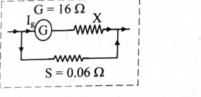
[Oct 13] A galvanometer has a resistance of 16 Ω. It shows full scale deflection when a current of 20 mA is passed through it. The only shunt resistance available is 0.06 Ω which is not appropriate to convert a galvanometer into an ammeter. How much resistance should be connected in series with the coil of galvanometer so that the range of ammeter is 8 A?
 Maharashtra HSC board questionAnswer 8 ↓
 - 9
[Mar 16] The combined resistance of a galvanometer of resistance 500 Ω and its shunt is 21 Ω. Calculate the value of shunt.
Maharashtra HSC board questionAnswer 9 ↓ - 10
[July 16] A moving coil galvanometer has a resistance of 25 Ω and gives a full scale deflection for a current of 10 mA. How will you convert it into a voltmeter having range 0–100 V?
Maharashtra HSC board questionAnswer 10 ↓ - 11
[Feb 24] A galvanometer has a resistance of 30 Ω and its full scale deflection current is 20 microampere (μA). What resistance should be added to it to have a range 0–10 volt?
Maharashtra HSC board questionAnswer 11 ↓
Answers & Solutions
Work the questions above first, then check yourself here. Each answer is set out the way it should be written in the paper.
i. To use a M.C.G as a voltmeter, a high resistance is connected in series with the M.C.G. ii. A very high resistance X is connected in series with the galvanometer for this purpose as shown in figure. iii. If V is the voltage to be measured, then where is the current flowing through the galvanometer. iv. If voltage V is times voltage (voltage across galvanometer) then, Using this in equation (1),
Moving coil galvanometer is converted into an ammeter by connecting a low resistance in parallel with the galvanometer, which effectively reduces the resistance of the galvanometer. This low resistance connected in parallel is called as shunt (S).
i. To use a M.C.G as an ammeter, a shunt (low resistance) is connected in parallel to the coil of M.C.G. ii. In the arrangement as shown in the figure, I and are the current through the circuit and galvanometer respectively. Therefore, the current through shunt S is, iii. Since S and G are parallel, potential difference across them is same. Equation (1) is useful to calculate the range of current that the galvanometer can measure. iv. If the current I is n times current , then . Using this in equation (1), This is the required shunt to increase the range n times. v. If is the current through the shunt resistance, then the remaining current will flow through galvanometer. This equation gives the fraction of the total current through the shunt resistance.
[From 9.5, Q3]
i. To use a M.C.G as an ammeter, a shunt (low resistance) is connected in parallel to the coil of M.C.G. ii. In the arrangement as shown in the figure, I and are the current through the circuit and galvanometer respectively. Therefore, the current through shunt S is, iii. Since S and G are parallel, potential difference across them is same. Equation (1) is useful to calculate the range of current that the galvanometer can measure. iv. If the current I is n times current , then . Using this in equation (1), This is the required shunt to increase the range n times. v. If is the current through the shunt resistance, then the remaining current will flow through galvanometer. This equation gives the fraction of the total current through the shunt resistance.[(i),(ii),(iii) and (iv)]
Ammeter Voltmeter a. It measures current. It measures potential difference b. It is connected in series. It is connected in parallel. c. It is an MCG with low resistance. (Ideally zero) It is an MCG with high resistance. (Ideally infinite) d. Smaller the shunt, greater will be the current measured. Larger its resistance, greater will be the potential difference measured. e. Resistance of ammeter, Resistance of voltmeter, [Any two points of differences]
For an ideal voltmeter the value of resistance is infinite.
Given: G = 500 Ω, V = 100 V, V To find: High resistance (R) Formula: R = G(n−1) Calculation: We know that, Now, using formula we get, R = 500(20−1) = 500×19 Ans: Given voltmeter can be made to measure a maximum voltage of 100 V by connecting a resistance of 9500 Ω in series with it.
Let 'X' be the resistance connected in series with galvanometer. Here S is not sufficient for I = 8 A. From the figure, Ans: A resistance of 7.94 Ω should be connected in series with coil of galvanometer.
Given: G = 500 Ω, To find: Shunt resistance (S) Formula: Calculation: From formula, Ans: The value of shunt resistance is 21.93 Ω.
Given: G = 25 Ω, mA = A, V = 100 V To find: Resistance () Formula: Calculation: From formula, Ans: A resistance of 9975 Ω should be connected in series.
Given: G = 30 Ω, A, maximum voltage V = 10 V To find: Resistance (X) Formula: Calculation: From formula, Ans: Resistance to be added is Ω.