12.15
Transformer
Electromagnetic Induction · Maharashtra HSC
Theory
What a transformer is
- A transformer is a device used for changing the voltage of alternating current from a low value to a high value or vice versa. Stated the way the board prints it: a transformer is an electrical device which converts low alternating voltage at high current into high alternating voltage at low current, and vice versa.
- Mutual inductance is the basis of all types of transformers.
Principle
- The working of a transformer is based on the principle of mutual induction: whenever the magnetic flux linked with a coil changes, an emf is induced in the neighbouring coil.
Construction
- A transformer consists of two sets of coils, primary P and secondary S, insulated from each other. The coil P is called the input coil and the coil S the output coil.
- The two coils are wound separately on a laminated soft-iron core.
- In a step-up transformer the number of turns in the secondary coil is greater than the number of turns in the primary coil .
- Diagram in words: a rectangular closed soft-iron core drawn as a stack of laminations; the primary winding P on the left limb with its two terminals going to the AC input, the secondary winding S on the right limb with its two terminals going to the output; for a step-up transformer S is drawn with visibly more turns than P.
Working
- When an alternating voltage is applied to the primary coil, the current through the coil goes on changing. Hence the magnetic flux through the core also changes.
- As this changing magnetic flux is linked with both the coils, an emf is induced in each coil.
- The amount of magnetic flux linked with a coil depends upon the number of turns of the coil.
Derivation of the transformer equation
- Let be the magnetic flux linked per turn with both the coils at a certain instant , and let and be the number of turns of the primary and secondary coils.
- Then at that instant the flux linked with the primary coil is and the flux linked with the secondary coil is .
- The induced emfs are
- Dividing equation (2) by equation (1),
- Equation (3) is the equation of the transformer. The ratio is called the turns ratio (transformer ratio) of the transformer.
- For an ideal transformer, input power output power:
- Combining equations (3) and (4),
The two cases
- Case 1: when , then — a step-up transformer — and , so the current in the primary coil is more than that in the secondary coil.
- Case 2: when , then — a step-down transformer — and , so the current in the primary coil is less than that in the secondary coil.
Distinguish between step-up and step-down transformer
| No. | Step-up transformer | Step-down transformer |
|---|---|---|
| i. | The number of turns in its secondary is more than that in its primary (). | The number of turns in primary is greater than secondary (). |
| ii. | Alternating voltage across the ends of its secondary is more than that across its primary, i.e. . | Alternating voltage across the ends of the primary is more than that across its secondary, i.e. . |
| iii. | Transformer ratio . | Transformer ratio . |
| iv. | Primary coil made of thick wire. | Secondary coil made of thick wire. |
| v. | Secondary coil is made of thin wire. | Primary coil is made of thin wire. |
| vi. | Current through secondary is less than primary. | Current through primary is less than secondary. |
Standard results
- Principle: mutual induction. Core: laminated soft iron. Works on AC only — with DC the flux is steady and no emf is induced in the secondary.
- , the turns ratio.
- An ideal transformer changes voltage and current in inverse proportion, leaving the power unchanged.
Theory Questions Asked on This Subtopic
Real board questions. Answers are at the end of the page.
- 1
State the principle on which a transformer works. With neat diagram, explain the construction of a step-up transformer.
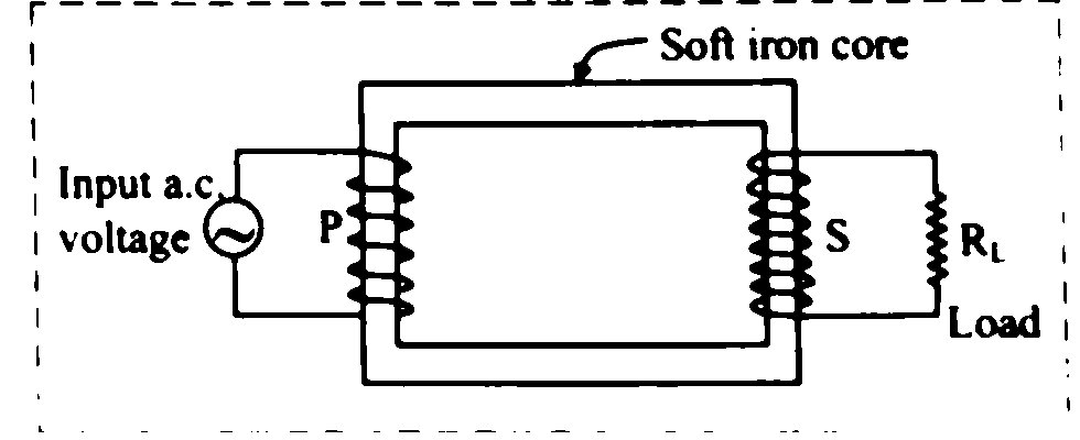 Maharashtra HSC board question — asked in March 2010Answer 1 ↓
 - 2
State the principle of a transformer. Explain its construction and working. Derive an expression for the ratio of e.m.f.s in terms of number of turns in primary and secondary coil. OR State the principle on which transformer works. Explain its working with construction. Derive an expression for ratio of e.m.f.s and currents in terms of number of turns in primary and secondary coil. OR State the principle of working of transformer. Explain the construction and working of a transformer. Derive an expression for e.m.f. and current in terms of turns ratio.
Maharashtra HSC board question — asked in July 2017; March 2014; March 2016Answer 2 ↓ - 3
Distinguish between step-up and step-down transformer.
Maharashtra HSC board question — asked in March 2009Answer 3 ↓ - 4
What is a transformer? With the help of a suitable diagram describe working of transformer.
Maharashtra HSC board question — asked in July 2022Answer 4 ↓ - 5
What is a transformer? State the working principle of transformer. Hence, distinguish between Step up and Step down transformer. (Any Two points).
Maharashtra HSC board question — asked in July 2023Answer 5 ↓ - 6
What is a transformer? Explain construction and working of a transformer. Derive the equation for a transformer.
Maharashtra HSC board question — asked in February 2024Answer 6 ↓
Answers & Solutions
Work the questions above first, then check yourself here. Each answer is set out the way it should be written in the paper.
Principle: Working of a transformer is based on the principle of mutual induction i.e., whenever the magnetic flux linked with a coil changes, an e.m.f is induced in the neighbouring coil. Construction: i. A step-up transformer consists of two sets of coils primary P and secondary S insulated from each other. The number of turns in secondary coil is greater than the number of turns in primary coil . The coil P is called the input coil and coil S is called the output coil. ii. The two coils are wound separately on a laminated soft iron core.
[From 12.15, Q1] Principle: Working of a transformer is based on the principle of mutual induction i.e., whenever the magnetic flux linked with a coil changes, an e.m.f is induced in the neighbouring coil. Construction: i. A step-up transformer consists of two sets of coils primary P and secondary S insulated from each other. The number of turns in secondary coil is greater than the number of turns in primary coil . The coil P is called the input coil and coil S is called the output coil. ii. The two coils are wound separately on a laminated soft iron core.for Principle. i. Construction: a. A transformer consists of two sets of coils primary P and secondary S insulated from each other. The coil P is called the input coil and coil S is called the output coil. b. The two coils are wound separately on a laminated soft iron core. ii. Working: a. When an alternating voltage is applied to the primary coil the current through the coil goes on changing. Hence, the magnetic flux through the core also changes. b. As this changing magnetic flux is linked with both the coils, an e.m.f is induced in each coil. c. The amount of the magnetic flux linked with the coil depends upon the number of turns of the coil. d. Let, '' be the magnetic flux linked per turn with both the coils at certain instant 't'. e. Let '' and '' be the number of turns of primary and secondary coil, = magnetic flux linked with the primary coil at certain instant 't' = magnetic flux linked with the secondary coil at certain instant 't' f. Induced e.m.f produced in the primary and secondary coil is given by, g. Dividing equation (2) by (1), Equation (3) represents equation of transformer. The ratio is called turns ratio (transformer ratio) of the transformer. h. For an ideal transformer, Input power = Output power i. From equation (3) and (4),
No. Step-up transformer Step-down transformer i. The number of turns in its secondary is more than that in its primary (). The number of turns in primary is greater than secondary (). ii. Alternating voltage across the ends of its secondary is more than that across its primary i.e., Alternating voltage across the ends of the primary is more than that across its secondary i.e., iii. Transformer ratio K > 1. Transformer ratio K < 1. iv. Primary coil made of thick wire. Secondary coil made of thick wire. v. Secondary coil is made of thin wire. Primary coil is made of thin wire. vi. Current through secondary is less than primary. Current through primary is less than secondary. Transformer: Transformer is an electrical device which converts low alternating voltage at high current to high alternating voltage at low current and vice-versa. Working: [From 12.15, Q2 (Diagram and working only)] [From 12.15, Q1] Principle: Working of a transformer is based on the principle of mutual induction i.e., whenever the magnetic flux linked with a coil changes, an e.m.f is induced in the neighbouring coil. Construction: i. A step-up transformer consists of two sets of coils primary P and secondary S insulated from each other. The number of turns in secondary coil is greater than the number of turns in primary coil . The coil P is called the input coil and coil S is called the output coil. ii. The two coils are wound separately on a laminated soft iron core.for Principle. i. Construction: a. A transformer consists of two sets of coils primary P and secondary S insulated from each other. The coil P is called the input coil and coil S is called the output coil. b. The two coils are wound separately on a laminated soft iron core. ii. Working: a. When an alternating voltage is applied to the primary coil the current through the coil goes on changing. Hence, the magnetic flux through the core also changes. b. As this changing magnetic flux is linked with both the coils, an e.m.f is induced in each coil. c. The amount of the magnetic flux linked with the coil depends upon the number of turns of the coil. d. Let, '' be the magnetic flux linked per turn with both the coils at certain instant 't'. e. Let '' and '' be the number of turns of primary and secondary coil, = magnetic flux linked with the primary coil at certain instant 't' = magnetic flux linked with the secondary coil at certain instant 't' f. Induced e.m.f produced in the primary and secondary coil is given by, g. Dividing equation (2) by (1), Equation (3) represents equation of transformer. The ratio is called turns ratio (transformer ratio) of the transformer. h. For an ideal transformer, Input power = Output power i. From equation (3) and (4),
Transformer: [From 12.15, Q4 (Definition only)] Transformer: Transformer is an electrical device which converts low alternating voltage at high current to high alternating voltage at low current and vice-versa. Working: [From 12.15, Q2 (Diagram and working only)] [From 12.15, Q1] Principle: Working of a transformer is based on the principle of mutual induction i.e., whenever the magnetic flux linked with a coil changes, an e.m.f is induced in the neighbouring coil. Construction: i. A step-up transformer consists of two sets of coils primary P and secondary S insulated from each other. The number of turns in secondary coil is greater than the number of turns in primary coil . The coil P is called the input coil and coil S is called the output coil. ii. The two coils are wound separately on a laminated soft iron core.for Principle. i. Construction: a. A transformer consists of two sets of coils primary P and secondary S insulated from each other. The coil P is called the input coil and coil S is called the output coil. b. The two coils are wound separately on a laminated soft iron core. ii. Working: a. When an alternating voltage is applied to the primary coil the current through the coil goes on changing. Hence, the magnetic flux through the core also changes. b. As this changing magnetic flux is linked with both the coils, an e.m.f is induced in each coil. c. The amount of the magnetic flux linked with the coil depends upon the number of turns of the coil. d. Let, '' be the magnetic flux linked per turn with both the coils at certain instant 't'. e. Let '' and '' be the number of turns of primary and secondary coil, = magnetic flux linked with the primary coil at certain instant 't' = magnetic flux linked with the secondary coil at certain instant 't' f. Induced e.m.f produced in the primary and secondary coil is given by, g. Dividing equation (2) by (1), Equation (3) represents equation of transformer. The ratio is called turns ratio (transformer ratio) of the transformer. h. For an ideal transformer, Input power = Output power i. From equation (3) and (4), Working Principle: [From 12.15, Q1 (Principle only)] Principle: Working of a transformer is based on the principle of mutual induction i.e., whenever the magnetic flux linked with a coil changes, an e.m.f is induced in the neighbouring coil. Construction: i. A step-up transformer consists of two sets of coils primary P and secondary S insulated from each other. The number of turns in secondary coil is greater than the number of turns in primary coil . The coil P is called the input coil and coil S is called the output coil. ii. The two coils are wound separately on a laminated soft iron core. Distinguish between Step up and Step down transformer: [From 12.15, Q3]
No. Step-up transformer Step-down transformer i. The number of turns in its secondary is more than that in its primary (). The number of turns in primary is greater than secondary (). ii. Alternating voltage across the ends of its secondary is more than that across its primary i.e., Alternating voltage across the ends of the primary is more than that across its secondary i.e., iii. Transformer ratio K > 1. Transformer ratio K < 1. iv. Primary coil made of thick wire. Secondary coil made of thick wire. v. Secondary coil is made of thin wire. Primary coil is made of thin wire. vi. Current through secondary is less than primary. Current through primary is less than secondary. Construction, working and equation: [From 12.15, Q2 (i)] [From 12.15, Q1] Principle: Working of a transformer is based on the principle of mutual induction i.e., whenever the magnetic flux linked with a coil changes, an e.m.f is induced in the neighbouring coil. Construction: i. A step-up transformer consists of two sets of coils primary P and secondary S insulated from each other. The number of turns in secondary coil is greater than the number of turns in primary coil . The coil P is called the input coil and coil S is called the output coil. ii. The two coils are wound separately on a laminated soft iron core.for Principle. i. Construction: a. A transformer consists of two sets of coils primary P and secondary S insulated from each other. The coil P is called the input coil and coil S is called the output coil. b. The two coils are wound separately on a laminated soft iron core. ii. Working: a. When an alternating voltage is applied to the primary coil the current through the coil goes on changing. Hence, the magnetic flux through the core also changes. b. As this changing magnetic flux is linked with both the coils, an e.m.f is induced in each coil. c. The amount of the magnetic flux linked with the coil depends upon the number of turns of the coil. d. Let, '' be the magnetic flux linked per turn with both the coils at certain instant 't'. e. Let '' and '' be the number of turns of primary and secondary coil, = magnetic flux linked with the primary coil at certain instant 't' = magnetic flux linked with the secondary coil at certain instant 't' f. Induced e.m.f produced in the primary and secondary coil is given by, g. Dividing equation (2) by (1), Equation (3) represents equation of transformer. The ratio is called turns ratio (transformer ratio) of the transformer. h. For an ideal transformer, Input power = Output power i. From equation (3) and (4), and (ii)