12.14
Mutual Inductance (M)
Electromagnetic Induction · Maharashtra HSC
Theory
The set-up
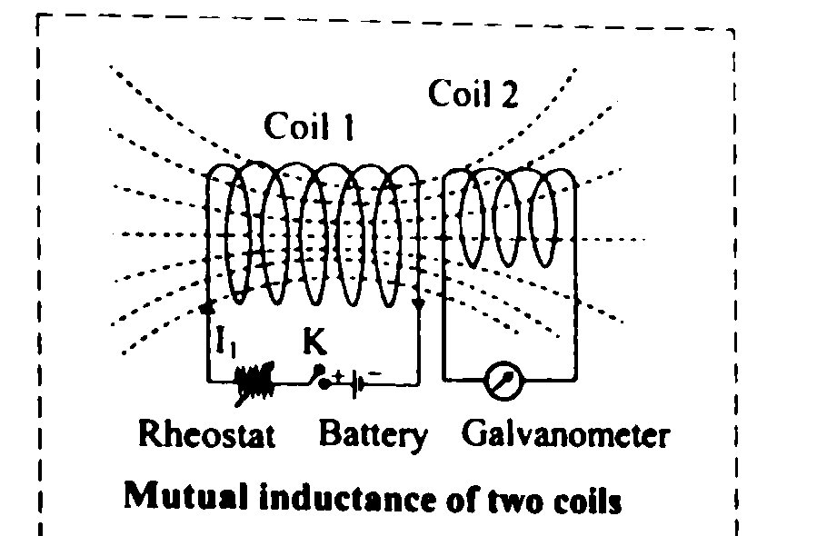
- Consider two coils placed side by side. Suppose a fixed current flows through coil 1; because of it a magnetic field is produced in the region surrounding coil 1, and part of it threads coil 2.
- Diagram in words: two coaxial coils facing each other a short distance apart; coil 1 carries from a source, and the field lines it produces spread out, some of them passing through the area enclosed by coil 2.
- The circuit in which the current is provided by an external source is called the primary; the other is the secondary.
Definition and derivation
- The magnetic flux linked with the surface area of coil 2 due to is
- If the positions of the coils are fixed in space, then , so
- where is a constant of proportionality termed the mutual inductance (coefficient of mutual induction) of coil 2 with respect to coil 1.
- Suppose changes slowly with time. Then the field in the vicinity of coil 2 is related to in the same way as it would be for a steady current, and changes in proportion as changes. The induced emf in coil 2 is
- Now let a current flow through coil 2 instead. The flux linked with coil 1 is proportional to :
- and the induced emf in coil 1 is
- By symmetry, .
Alternative definitions of mutual inductance
- From and ,
- Hence the mutual inductance of two circuits is equal to the magnetic flux linked with one circuit per unit current in the other. In primary-secondary language,
- The mutual inductance of two circuits is the magnetic flux linked with the secondary circuit per unit current in the primary circuit.
- From Faraday's law applied to the secondary,
- Hence mutual inductance is also defined as the value of the induced emf produced in the secondary circuit per unit rate of change of current in the primary circuit.
- Mutual potential energy: it can be shown that the mutual potential energy of two circuits is , so may also be defined as the mutual potential energy of two circuits corresponding to unit current flowing in each: , and when .
Unit of mutual inductance
- The unit is the henry (H).
- If, corresponding to a rate of change of current of in the primary circuit, the induced emf produced in the secondary circuit is 1 volt, then the mutual inductance of the two circuits is 1 henry.
Self induction and mutual induction compared
| Point | Self induction | Mutual induction |
|---|---|---|
| Number of coils | One coil, acting on itself | Two neighbouring coils |
| Cause of the emf | Change of current in the same coil | Change of current in the primary coil |
| Coefficient | ||
| Induced emf | ||
| Depends on | Geometry and core of that coil | Geometry, core, separation and relative orientation of both coils |
Coefficient of coupling
- The coefficient of coupling is a measure of the portion of the flux of coil 1 that actually reaches coil 2. The greater the coefficient of coupling, the greater the mutual inductance.
- Since the inductance of any circuit is proportional to the induced voltage it can develop, , where is the emf developed in coil 2 due to the portion of coil 1's flux reaching it.
- The induced emf is also proportional to the number of turns, so ; and , so .
- Also , so , giving . Replacing by ,
- is usually less than unity. If the two coils are perfectly coupled and .
- : tightly coupled. : loosely coupled. If , a coil coupled to itself has .
- Expressed as a percentage, is the percentage of the flux from one coil that reaches the other.
- Theoretically the coupling is never perfect. Two coils wound on a common iron core may be taken to have . For air-core coils or coils on separate iron cores, depends on the distance between the coils and the angle between their axes: is maximum when the coils are parallel and in line (coaxial), and minimum when their axes are at right angles and in line. To prevent interaction, coils should be at right angles to each other and as far apart as possible. For radio-frequency and intermediate-frequency transformer coils, lies between 0.001 and 0.05.
- A large is desirable in a transformer but not in a home appliance. In an electric clothes dryer a dangerous emf could be induced on the metallic case if the mutual inductance between the heating coils and the case were large, so the heating coils are counter-wound: their magnetic fields cancel one another and with the case is reduced.
Standard geometries
- Solenoid with a small coil wound round its centre: with turns on the solenoid of length and area , and turns on the secondary, , the flux linkage of the secondary is , and
- Wireless battery charger: the base unit is a solenoid (coil B) of length with turns carrying current and cross-section ; the handle coil (coil H) of turns surrounds it completely. With and , the flux linkage is and
Why two coils in parallel have less inductance than either
- For a parallel combination, the current through each parallel inductor is only a fraction of the total current, while the voltage across each parallel inductor is the same.
- As a result, a given change in the total current develops less voltage across the parallel array than it would across any one of the individual inductors.
- There is therefore less voltage drop across the parallel inductors for a given rate of change of current than across any of the individual inductors.
- Less voltage for the same rate of change of current means less inductance.
- Hence the total inductance of two coils in parallel is less than the inductance of either coil, consistent with .
Standard results
- , , .
- ; unit henry ohm second.
- with ; for a solenoid and a coil wound round it.
Theory Questions Asked on This Subtopic
Real board questions. Answers are at the end of the page.
- 1
Explain self induction and mutual induction.
 Maharashtra HSC board question — asked in March 2017Answer 1 ↓
 - 2
Explain, why the equivalent inductance of two coils connected in parallel is less than the inductance of either of the coils.
Maharashtra HSC board question — asked in February 2023Answer 2 ↓
Numericals
Every numerical set on this subtopic. Full working is at the end of the page.
- 3
The co-efficient of mutual induction between primary and secondary coil is 2 H. Calculate induced e.m.f. if current of 4 A is cut off in seconds.
Maharashtra HSC board question — asked in March 2016Answer 3 ↓ - 4
An emf of 91 mV is induced in the windings of a coil, when the current in a nearby coil is increasing at the rate of 1.3 A/s, what is the mutual inductance (M) of the two coils in mH?
Maharashtra HSC board question — asked in March 2022Answer 4 ↓ - 5
An emf of 96.0 mV is induced in the windings of a coil when the current in a nearby coil is increasing at the rate of 1.20 A/s. What is the mutual inductance (M) of the coils?
Maharashtra HSC board question — asked in July 2022Answer 5 ↓
Answers & Solutions
Work the questions above first, then check yourself here. Each answer is set out the way it should be written in the paper.
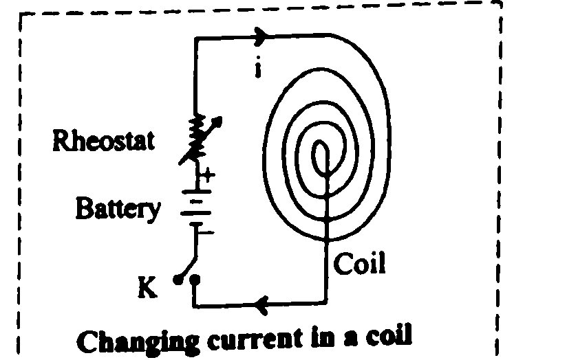
i. Self-induction: a. Consider a circuit (coil) in which the current is changing. b. The changing current will vary the magnitude of magnetic flux linked with the coil (circuit) itself and consequently an emf will be induced in the circuit. c. The production of induced emf, in the circuit (coil) itself, on account of a change in the current in it, is termed as the phenomenon of self-inductance. d. Let at any instant, the value of magnetic flux linked with the circuit itself be corresponding to current I in it. i.e., where L is a constant of proportionality and is termed as the self-inductance (or coefficient of self induction) of the coil. e. For a closely wound coil of N turns, the same magnetic flux will be linked with all the turns. When the flux through the coil changes, each turn of the coil contributes towards the induced emf. f. The flux linkage for a coil with N turns corresponding to current I will be written as, g. The inductance (L) depends only on the geometry and material properties of the coil. h. According to Faraday's law, induced emf e is given by, Using equation (1), ii. Mutual induction: a. Consider a case of two coils placed side by side as shown in figure. b. Suppose a fixed current is flowing through coil 1. Due to this current a magnetic field (x,y,z) will be produced in the nearby region surrounding the coil 1. c. Magnetic flux linked with the surface area of the coil 2 due to magnetic field is given as, d. If the positions of the coils are fixed in space, Then where, = constant of proportionality termed as mutual inductance or coefficient of mutual induction of coil 2 (or circuit ) with respect to coil 1 (or circuit ). e. Suppose changes slowly with time then magnetic field in the vicinity of coil 2 is related to current I in coil 1 in the same way as it would be related for a steady current. The magnetic flux will change in proportion as changes. f. The induced emf in coil 2 is given as, g. When current flows through coil 2, magnetic flux linked with coil 1 is given as, Where, = mutual inductance of coil 1 with respect to coil 2. h. The induced emf in coil 1 will be,
i. For parallel combination of two coils, the current through each parallel inductor is a fraction of the total current and the voltage across each parallel inductor is same. ii. As a result, a change in total current will result in less voltage dropped across the parallel array than for any one of the individual inductors. iii. There will be less voltage drop across parallel inductors for a given rate of change in current than for any of the individual inductors. iv. Less voltage for the same rate of change in current results in less inductance. v. Thus, the total inductance of two coils is less than the inductance of either coil.
Given: H, A, s To find: induced e.m.f.(e) Formula: Calculation: From formula, Ans: The induced e.m.f. in the coil is V.
Given: mV V, A/s To find: Mutual Inductance (M) Formula: Calculation: From formula Ans: Mutual Inductance of the two coils is 70 mH.
Given: mV V, A/s To find: Mutual Inductance (M) Formula: Calculation: From formula Ans: Mutual Inductance of the two coils is 80 mH.