Chapter 13
AC Circuits
Maharashtra HSC · 10 subtopics · textbook pages 288–305
Formula SheetEvery formula this chapter can be examined on, in one table.
AC Generator — Alternating emf and Current
| Formula | Symbols, units and conditions |
|---|---|
| |
| |
|
Average and RMS Values
| Formula | Symbols, units and conditions |
|---|---|
| |
| |
| |
|
AC Voltage Applied to a Resistor
| Formula | Symbols, units and conditions |
|---|---|
| |
|
AC Voltage Applied to an Inductor
| Formula | Symbols, units and conditions |
|---|---|
| |
|
AC Voltage Applied to a Capacitor
| Formula | Symbols, units and conditions |
|---|---|
| |
|
Series LCR Circuit
| Formula | Symbols, units and conditions |
|---|---|
| |
| |
| |
| — | |
| |
| |
|
Power in an AC Circuit
| Formula | Symbols, units and conditions |
|---|---|
| — | |
| |
| |
| |
| |
|
LC Oscillations
| Formula | Symbols, units and conditions |
|---|---|
| |
| |
| |
|
Electric Resonance
| Formula | Symbols, units and conditions |
|---|---|
| |
| |
| |
|
Sharpness of Resonance — Q Factor
| Formula | Symbols, units and conditions |
|---|---|
| |
| |
|
Choke Coil
| Formula | Symbols, units and conditions |
|---|---|
| — | |
|
Short NotesThe chapter subtopic by subtopic, in the textbook's own order.10 subtopics
- 1Introduction
- 2AC Generator1 board question
- 3Average and RMS Values1 board question
- 4Phasors
- 5Different types of AC circuits7 board questions
- 6Power in AC circuit4 board questions
- 7LC Oscillations
- 8Electric Resonance8 board questions
- 9Sharpness of Resonance: Q Factor
- 10Choke Coil
The whole chapter in brief
13.1 Introduction
- DC (direct current): the polarity of the supply voltage is fixed — the positive and negative ends of the supply do not change.
- AC (alternating current): the polarity of the voltage keeps reversing periodically.
- Electricity is supplied mostly as AC because it is cheap to generate and convenient to transport.
- Appliances such as TV, computer and radio use a rectifier to convert AC to DC; fans, fridges, air conditioners and heaters run directly on AC.
- Remember this: an AC shock is attractive while a DC shock is repulsive, so 220 V AC is more dangerous than 220 V DC. Also 220 V AC has a peak value of V, whereas DC has a fixed value of 220 V only.
13.2 AC Generator
- An AC generator produces a time-dependent emf , where is the peak emf and the angular frequency of rotation of the coil.
- The current in the connected circuit has the same time dependence: , with the phase difference between current and emf.
- Graph of against is a sine curve: the direction of the emf reverses after every half revolution of the coil. Such an emf is called alternating emf and the corresponding current alternating current.
- Peak value: the maximum value of the alternating current (or emf) in either direction.
- The average value of alternating current or emf over a complete cycle is zero.
13.3 Average and RMS Values
- Average value of AC is defined over one half cycle, because over a full cycle the average of — and hence of the AC — is zero and carries no meaning.
- Average value of over to is , so and .
- A moving-coil ammeter or voltmeter responds to the average value, so it cannot measure AC. What is needed is a property independent of the direction of flow — the heating effect, which depends on the square of the current.
- RMS (effective, virtual) value: the value of that steady current which produces the same heat in the same resistance in the same time as the given AC does.
- and .
- Heat produced by a sinusoidal AC over a complete cycle is — the same as that produced by a DC of magnitude for the same time.
- All AC ammeters, voltmeters and quoted supply ratings (220 V, 110 V) are rms values.
13.4 Phasors
- A rotating vector that represents a sinusoidally varying quantity is called a phasor; the diagram representing it is a phasor diagram.
- The length of the arrow represents the peak value of the quantity ( or ); the phasor is inclined at (or ) to the horizontal axis and rotates anticlockwise.
- The projection of the phasor on a fixed axis gives the instantaneous value: on the Y-axis for the sine form, on the X-axis for the cosine form.
- Representing emf and current as rotating vectors lets us add them by the laws of vector addition, which is why phasors simplify AC circuit analysis.
13.5 Different Types of AC Circuits
Resistor alone
- gives , with .
- Current and emf are in phase — both reach zero, minimum and maximum at the same instants.
- behaves identically for AC and DC, and can reduce both equally effectively.
- Phasor diagram: the phasors for and point in the same direction, making an angle with OX; phase angle between them is zero.
Inductor alone
- Applied emf opposes the self-induced emf . With no resistance, Kirchhoff's voltage law gives ; integrating (the constant of integration is zero, since must oscillate about zero) gives with .
- Current lags the emf by rad (90°); equivalently the voltage across leads the current by 90°.
- Inductive reactance: , the opposing nature of an inductor to the flow of AC. SI unit ohm; dimensions the same as those of resistance.
- and . For DC, , so — a pure inductor cannot reduce DC. It passes DC and blocks high-frequency AC.
- Phasor diagram: the phasor is turned 90° clockwise from the phasor.
Capacitor alone
- , so with .
- Current leads the emf by rad (90°).
- Capacitive reactance: . It is defined as the ratio of the rms voltage across the capacitor to the corresponding rms current. SI unit ohm.
- and . For DC, , so — a capacitor blocks DC and acts as an open circuit, while it passes high-frequency AC.
- Phasor diagram: the phasor is turned 90° anticlockwise from the phasor.
| Resistance | Reactance |
|---|---|
| Equally effective for AC and DC | Current is reduced but no energy is consumed; heat is generated only by the resistive component |
| Value is independent of the frequency of the AC | is directly proportional and inversely proportional to the frequency |
| Current opposed by a resistor is in phase with the voltage | Current opposed by a pure inductor lags, and by an ideal capacitor leads, the voltage by |
Series LCR circuit
- The same current flows through all three; the voltages are (in phase with ), (leads by 90°) and (lags by 90°).
- and are 180° out of phase, so the net reactive voltage is .
- Phasor addition gives .
- Impedance , in ohm; it is the ratio of rms voltage to rms current. Its reciprocal is admittance, unit ohm or siemens.
- , where is the angle by which the voltage leads the current.
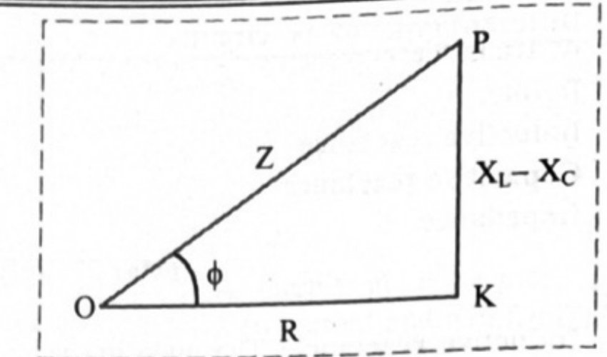
- Impedance triangle: base , perpendicular , hypotenuse , angle at the base .
| Case | Sign of | Nature of circuit |
|---|---|---|
| zero | Voltage and current in phase; non-inductive (purely resistive) | |
| positive | Voltage leads the current; inductance dominated | |
| negative | Voltage lags the current; capacitance dominated |
13.6 Power in an AC Circuit
- Instantaneous power ; because both change every instant, the useful quantity is the average over one full cycle.
- Pure resistor: , and since , . This product is also called the apparent power.
- Pure inductor: , so , and , giving .
- Ideal capacitor: , so , and again .
- Series LCR: — the true power.
- Power factor true power / apparent power .
- () for a non-inductive circuit; () for a pure inductor or ideal capacitor.
- Wattless (idle) current: the current through a pure inductor or an ideal capacitor, which consumes no power for its maintenance in the circuit. Power is dissipated only in the resistance.
- A low power factor in a transmission line means a large current is needed to deliver the same power, and the loss in the line therefore becomes large.
13.7 LC Oscillations
- A charged capacitor connected across a resistanceless inductor sets up electrical oscillations of constant amplitude and frequency, called LC oscillations.
- Energy surges back and forth between the electric field of the capacitor, , and the magnetic field of the inductor, .
- Stage by stage: capacitor fully charged with (all energy electrostatic, ); capacitor discharges and grows (energy shared); capacitor fully discharged and (all energy magnetic, ); flux decreases and the induced emf drives the current in the same direction, charging the capacitor with reversed polarity; the process then repeats in the opposite direction and the circuit returns to its initial state.
- Frequency: . Maximum current from energy conservation: .
- If there is no loss of energy the amplitude stays constant and the oscillations are undamped.
- In practice LC oscillations are damped, for two reasons: (a) every inductor has some resistance, so energy is lost as heat and the amplitude dies out; (b) even with zero resistance, energy is radiated away as electromagnetic waves — the basis of radio and TV transmitters.
13.8 Electric Resonance
- Resonance occurs when a system with a natural frequency of oscillation is driven by a source whose frequency equals that natural frequency; the amplitude of oscillation then becomes large.
- Series resonance circuit: , and in series, admitting maximum current for a given AC frequency.
- As rises, increases and decreases; at they are equal, so , the least possible value.
- gives and .
- Series resonance curve: rms current plotted against frequency, peaking sharply at . The peak height is , so a smaller gives a taller, sharper peak.
- Parallel resonance circuit: coil and condenser in parallel across the source. The total current is , minimum when , i.e. at the same .
- Do you know: for resonance to occur, both and must be present, because only then do the mutually 180°-out-of-phase voltages across them cancel and the whole source voltage appear across . There is no resonance in an LR or a CR circuit.
| Series resonance | Parallel resonance |
|---|---|
| Occurs when | Occurs when |
| Impedance is minimum and equals | Impedance is maximum |
| Current is maximum | Current is minimum |
| Accepts one frequency and rejects others — acceptor circuit | Rejects and passes the others — rejector circuit |
| Circuit is purely resistive; and in phase | Used in wireless transmission, radio communication and filter circuits |
13.9 Sharpness of Resonance — Q Factor
- Current amplitude in a series LCR circuit is ; it is maximum when .
- Half-power frequencies: the two values of at which the current amplitude falls to of its maximum, so that the power dissipated is halved. They lie symmetrically about : and .
- Bandwidth .
- Q factor of a series resonant circuit is defined as the ratio of the resonant frequency to the difference between the two frequencies, taken one on either side of resonance, at which the current amplitude is times its value at resonance.
- ; it is dimensionless.
- Larger means smaller bandwidth, a sharper peak and a more selective circuit.
- On the resonance curve the low-frequency side is dominated by the capacitor's reactance and the high-frequency side by the inductor's reactance; resonance occurs in the middle.
- Tuning a radio or TV is an LCR resonance: the antenna picks up many frequencies, but maximum current flows for the one equal to . A large keeps other stations weak, and varying the adjustable capacitor tunes in the desired station.
13.10 Choke Coil
- Reducing AC with an ordinary resistance wastes energy as Joule heat (). A choke coil reduces the current without much loss of energy.
- Construction: thick insulated copper wire wound closely in a large number of turns over a soft-iron laminated core.
- It offers a large reactance to AC, so the current is reduced; the laminated core reduces eddy-current loss.
- Power dissipated with .
- is very large and very small, so is nearly zero and the power loss is very small.
- The only real loss is hysteresis loss in the core, reduced by using soft iron.
Standard One-Mark and Two-Mark Answers
- Brightness of a lamp in series with a capacitor when is increased: decreases, so decreases, current increases and the lamp glows brighter.
- Why the total impedance falls when a capacitor is added in series with and : acts opposite to , so the net reactance is smaller than alone and hence is smaller.
- Why a capacitor behaves like a pure conductor at very high frequency: as becomes very large, so it offers almost no opposition.
- Wattless current: the current in a pure inductor or ideal capacitor, where and , so it consumes no power.
- Natural frequency of an LC circuit is , and at this frequency , so the net reactance of the circuit is zero.
- In an LR circuit with , power factor . Adding a capacitor with makes the circuit purely resistive, so and .
Traps That Cost Marks
- Writing the average value of AC over a full cycle as . Over a full cycle it is zero; is the half-cycle average.
- Adding the voltages across , and arithmetically. They must be added as phasors: . The reading across or alone can even exceed the source voltage.
- Confusing and behaviour with frequency. rises with (inductor blocks high-frequency AC, passes DC); falls with (capacitor blocks DC, passes high-frequency AC).
- Forgetting the when converting: , not ; , not .
- Using the peak value where the question gives an rms value. A supply described as "220 V, 50 Hz" is rms; convert with before using .
- Treating the impedance at resonance as zero. It is minimum and equals , not zero.
- Interchanging the two resonance circuits: series is minimum , maximum current, acceptor; parallel is maximum , minimum current, rejector.
- Saying resonance can happen in an LR or CR circuit. Both and are essential.
- Forgetting to convert mH, F and pF to henry and farad before substituting. 1 mH H, 1 F F, 1 pF F.
- Quoting the power in a pure inductor or capacitor as . It is zero — the power factor is zero.
- Dropping from in an LCR numerical, which turns true power into apparent power.
- Leaving in degrees when a time lag is asked. needs in radian.
Solved Numerical ExamplesWorked numericals to attempt first, each with a hint before the full solution.Coming soon
These are being added chapter by chapter. They are solved numericals from the prescribed book and the reference guides — not previous board questions, which live under Practice — so that you can work through the method before meeting it in a real paper.
Important DerivationsEvery derive / obtain / prove question in this chapter. 2 have come up in two or more papers.5
- 1Impedance of a series LCR circuit connected to an AC source (phasor method) RepeatsDerive an expression for the impedance of an LCR circuit connected to an AC power supply. Draw the phasor diagram.
Asked in: July 2018; February 2024 (Q.21, 3 marks); July 2024 (Q.17, 3 marks); June 2025 (Q.28, 4 marks)
Show the derivationHide the derivation
Step 1A circuit in which inductance L, capacitance C and resistance R are connected in series and the circuit admits maximum current corresponding to a given frequency of AC, is called a series resonance circuit.Step 2The impedance (Z) of an LCR circuit is given by,Step 3At very low frequencies, inductive reactance is negligible but capacitive reactance is very high.Step 4As we increase the applied frequency then increases and decreases.Step 5At some angular frequency (),i.e.,Where is called the resonant frequency.Step 6At this particular frequency , since we get . This is the least value of Z.Step 7Thus, when the impedance of an LCR circuit is minimum, circuit is said to be purely resistive, current and voltage are in phase and hence the current is maximum. This condition of the LCR circuit is called resonance condition and this frequency is called series resonant frequency.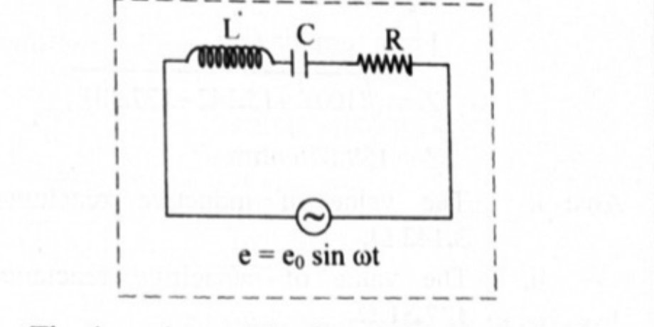
- 2Resonant frequency of a series resonant circuit RepeatsDerive an expression for the resonant frequency of a series resonant circuit.
Asked in: July 2018; February 2026 (Q.16, 3 marks)
Show the derivationHide the derivation
Step 1A circuit in which inductance L, capacitance C and resistance R are connected in series and the circuit admits maximum current corresponding to a given frequency of AC, is called a series resonance circuit.Step 2The impedance (Z) of an LCR circuit is given by,Step 3At very low frequencies, inductive reactance is negligible but capacitive reactance is very high.Step 4As we increase the applied frequency then increases and decreases.Step 5At some angular frequency (),i.e.,Where is called the resonant frequency.Step 6At this particular frequency , since we get . This is the least value of Z.Step 7Thus, when the impedance of an LCR circuit is minimum, circuit is said to be purely resistive, current and voltage are in phase and hence the current is maximum. This condition of the LCR circuit is called resonance condition and this frequency is called series resonant frequency. - 3Average power dissipated in a purely resistive AC circuit; power factorObtain an expression for the average power dissipated in a purely resistive A.C. circuit. Define the power factor of the circuit and state its value for a purely resistive A.C. circuit.
Asked in: October 2015
Show the derivationHide the derivation
Step 1Expression for average power in purely resistive circuit:a. Let, be applied e.m.f across a resistor of resistance 'R' as shown in figure. At certain instant, current is flowing through the resistor. In this case both 'e' and 'i' are in phase.b. Instantaneous power in circuit is given by,c. Average power for a complete cycle can be obtained by integrating equation (1).P is also called as apparent power.Step 2Power factor for a circuit is given by,In purely resistive circuit,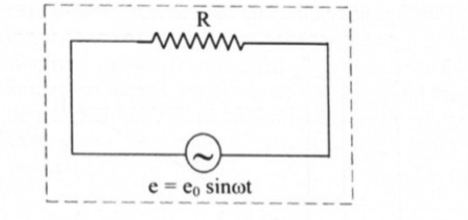
- 4Average power dissipated in a series LCR AC circuit; power factorObtain an expression for the average power dissipated in a series LCR A.C. circuit. Hence obtain an expression for the power factor of the circuit.
Asked in: July 2019
Show the derivationHide the derivation
Step 1Expression for average power dissipated in LCR circuit:a. Suppose that an alternating e.m.f is applied across an AC circuit containing L, C and R as shown in figure.b. In such circuit, there is a phase difference between applied emf and current. Therefore, the instantaneous current is given by, .c. Instantaneous power in the circuit is given by,This expression shows that P varies with t.d. Average power dissipated in the circuit can be obtained by integrating equation (1),e. Also,f. Substitute equations (3) and (4) in equation (2), we get,Equation (5) represents required average power or true power dissipated in the AC circuit.Step 2Power factor:a. Average power dissipated in LCR series circuit is given by,b. This implies that, the average power dissipated in LCR series circuit depends on the rms values of current and emf as well as the phase difference between them. The term is called power factor.c. It is given by,d. The average power is also termed as true power and product () is called apparent power.e. Consider impedance triangle for series LCR circuit as shown in figure,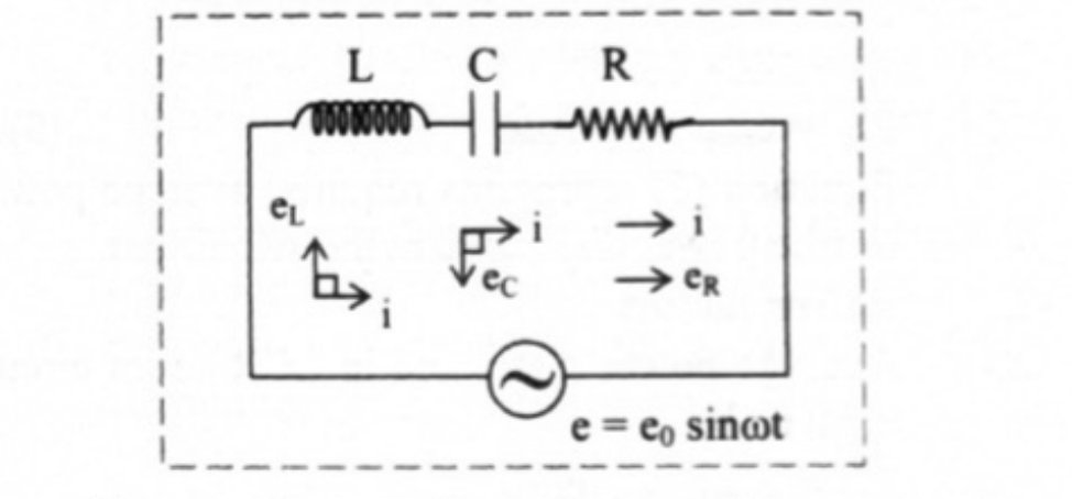
- 5Resonant frequency of a parallel resonant circuitAssuming the expression for impedance in a parallel resonant circuit, state the conditions for parallel resonance. Define resonant frequency and obtain an expression for it.
Asked in: March 2019
Show the derivationHide the derivation
Step 1A parallel resonance circuit is an AC circuit in which a parallel combination of an inductor and capacitor is connected to a source of an alternating e.m.f.Step 2Let the alternating emf supplied by the source be,Step 3In case of an inductor, the current lags behind the applied emf by a phase angle of , then the instantaneous current through L is given byStep 4Similarly in a capacitor, as current leads the emf by a phase angle of , we can writeStep 5Therefore, the total current i in the circuit at this instant is,Step 6Therefore, when , i = minimum,Where is called the resonant frequency.Step 7Conditions for parallel resonance to occur,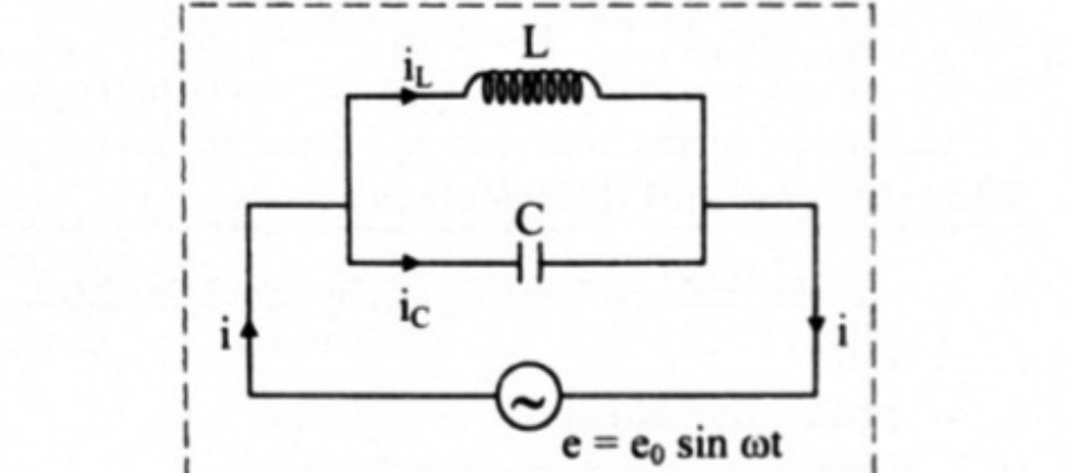
Finished revising this chapter? Practise AC Circuits →