13.8
Electric Resonance
AC Circuits · Maharashtra HSC
Theory
13.8 Electric Resonance
Resonance is observed in systems that have a tendency to oscillate at a particular frequency, called the natural frequency of oscillation of the system. When such a system is driven by an energy source whose frequency is equal to the natural frequency of the system, the amplitude of oscillation becomes large and resonance is said to occur. Tuning a radio to a station, and a glass shattering at a concert, are both examples.
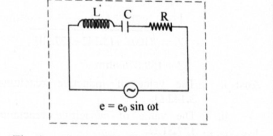
(a) Series Resonance Circuit
A circuit in which inductance , capacitance and resistance are connected in series, and which admits maximum current corresponding to a given frequency of AC, is called a series resonance circuit.
The impedance of an LCR circuit is
At very low frequencies the inductive reactance is negligible but the capacitive reactance is very high. As the applied frequency is increased, increases and decreases. At some angular frequency they become equal:
where is called the resonant frequency.
At this particular frequency, since , we get , which is the least value of . Thus when the impedance of an LCR circuit is minimum, the circuit is said to be purely resistive, the current and the voltage are in phase, and hence the current
is maximum. This condition of the LCR circuit is called the resonance condition and this frequency is called the series resonant frequency.
At the peak current is maximum, and its maximum value is inversely proportional to — for lower , is large, and vice versa.
Series resonance curve: a graph of rms current against the frequency of the AC. It rises to a sharp maximum at and falls off on either side; a smaller gives a taller and sharper peak. At resonance the rms current becomes maximum. The circuit at the resonant condition is very useful in radio and TV receivers for tuning in the signal from a desired transmitting station or channel.
Characteristics of a series resonance circuit
- Resonance occurs when .
- Resonant frequency .
- Impedance is minimum and the circuit is purely resistive.
- Current has a maximum value.
- When a number of frequencies are fed to it, it accepts only the one frequency and rejects the others; the current is maximum for this frequency. Hence it is called an acceptor circuit.
(b) Parallel Resonance Circuit
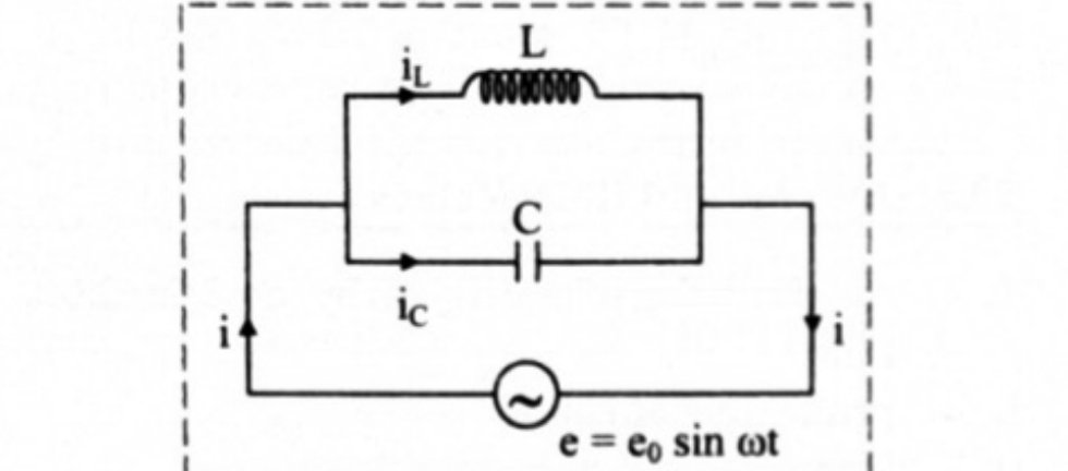
A parallel resonance circuit consists of a coil of inductance and a condenser of capacity joined in parallel to a source of alternating emf,
In the case of an inductor the current lags behind the applied emf by a phase angle of , so the instantaneous current through is
Similarly, in a capacitor the current leads the emf by , so
The total current in the circuit at this instant is
The current is minimum when
The condition for parallel resonance is therefore , i.e. — the same condition, and the same resonant frequency, as in the series case.
At the parallel resonant frequency the current is minimum: the circuit allows minimum current to flow through it, and the impedance is maximum. A parallel resonant circuit is very useful in wireless transmission or radio communication and in filter circuits.
Parallel resonance curve: a graph of current against frequency showing a sharp minimum (a dip) at — the mirror image of the series curve.
Characteristics of a parallel resonance circuit
- Resonance occurs when .
- Resonant frequency .
- Impedance is maximum.
- Current is minimum.
- When alternating currents of different frequencies are sent through it, it offers a very high impedance to the current of the resonant frequency and rejects it, but allows currents of other frequencies to pass. Hence it is called a rejector circuit.
Do You Know — Both L and C Are Essential
Resonance occurs in a series LCR circuit when , i.e. . For resonance to occur, the presence of both and in the circuit is essential. Only then will the voltages across and , being 180° out of phase, cancel each other and let the current amplitude become , so that the total source voltage appears across . So we cannot have resonance in an LR or a CR circuit.
Standard Results
- ; ; — the same for series and parallel, and independent of .
- Series: , , , acceptor circuit.
- Parallel: maximum, current minimum, rejector circuit.
- At series resonance the voltages across and across are equal in magnitude and opposite in phase, so ; each can be far larger than the source voltage.
Worked Pattern
mH, F: Hz. With and mV, at resonance A, and V .
H, F, , 120 V supply: at resonance , A, and Hz.
mH in parallel with F: Hz.
Theory Questions Asked on This Subtopic
Real board questions. Answers are at the end of the page.
- 1
What is series LCR resonant circuit? Obtain the expression for impedance. Hence state the conditions for series resonance and derive the expression for resonant frequency.
 Maharashtra HSC board question — asked in July 2018Answer 1 ↓
 - 2
Assuming expression for impedance in a parallel resonant circuit, state the conditions for parallel resonance. Define resonant frequency and obtain an expression for it.
 Maharashtra HSC board question — asked in March 2019Answer 2 ↓
 - 3
State the conditions for current and impedance in parallel resonance circuit.
Maharashtra HSC board question — asked in July 2023Answer 3 ↓
Numericals
Every numerical set on this subtopic. Full working is at the end of the page.
- 4
An LCR series combination has R = 10 , L = 1 mH and C = 2 F. Determine: i. The resonant frequency ii. the current in the circuit, and iii. Voltages across L and C, when an alternating voltage of 10 mV, operating at the resonant frequency, is applied to the series combination.
Maharashtra HSC board question — asked in March 2008Answer 4 ↓ - 5
An a.c circuit consists of inductor of 125 mH connected in parallel with a capacitor of 50 F. Determine resonant frequency.
Maharashtra HSC board question — asked in October 2014Answer 5 ↓ - 6
A parallel L-C circuit comprises of a 5 H inductor and 5 F capacitor. Calculate the resonant frequency of the circuit.
Maharashtra HSC board question — asked in February 2020Answer 6 ↓ - 7
A 0.1 H inductor, a F capacitor and a 15 resistor are connected in series to a 120 V, 50 Hz AC source. Calculate the resonant frequency.
Maharashtra HSC board question — asked in March 2022Answer 7 ↓ - 8
A 1000 mH inductor, 36 F capacitor and 12 resistor are connected in series to 120 V, 50 Hz AC source. Calculate: i. impedance of the circuit at resonance ii. current at resonance iii. resonant frequency
Maharashtra HSC board question — asked in July 2022Answer 8 ↓
Answers & Solutions
Work the questions above first, then check yourself here. Each answer is set out the way it should be written in the paper.
i. A circuit in which inductance L, capacitance C and resistance R are connected in series and the circuit admits maximum current corresponding to a given frequency of AC, is called a series resonance circuit. ii. The impedance (Z) of an LCR circuit is given by, iii. At very low frequencies, inductive reactance is negligible but capacitive reactance is very high. iv. As we increase the applied frequency then increases and decreases. v. At some angular frequency (), i.e., Where is called the resonant frequency. vi. At this particular frequency , since we get . This is the least value of Z. vii. Thus, when the impedance of an LCR circuit is minimum, circuit is said to be purely resistive, current and voltage are in phase and hence the current is maximum. This condition of the LCR circuit is called resonance condition and this frequency is called series resonant frequency.
i. A parallel resonance circuit is an AC circuit in which a parallel combination of an inductor and capacitor is connected to a source of an alternating e.m.f. ii. Let the alternating emf supplied by the source be, iii. In case of an inductor, the current lags behind the applied emf by a phase angle of , then the instantaneous current through L is given by iv. Similarly in a capacitor, as current leads the emf by a phase angle of , we can write v. Therefore, the total current i in the circuit at this instant is, vi. Therefore, when , i = minimum, Where is called the resonant frequency. vii. Conditions for parallel resonance to occur,
In parallel resonant circuit, current is minimum and impedance is maximum.
Given: , mH H, F F, mV V To find: i. Resonant frequency () ii. Current () iii. Voltage across L () iv. Voltage across C () Formulae: i. ii. iii. Calculation: From formula (i), From formula (ii), From formula (iii), V At resonance, V Ans: i. The resonant frequency is Hz ii. Current in the circuit is A iii. Voltage across L is V iv. Voltage across C is V.
Given: mH H, F F To find: Resonant frequency () Formula: Calculation: Using formula, Ans: The resonant frequency in the A.C. circuit is 63.69 Hz.
Given: H, F F To find: Resonant frequency () Formula: Calculation: Using formula, Ans: The resonant frequency in the A.C. circuit is 31.82 Hz.
Given: H, F, , V To find: Resonant frequency () Formula: Calculation: From formula, Hz Ans: The value of resonant frequency is 100.6 Hz.
Given: mH H, , F F, V To find: i. Impedance of the circuit (Z) ii. Current at resonance () iii. Resonant frequency () Formulae: i. ii. Calculation: At resonance, From formula (i), A From formula (ii), Hz Ans: i. The Impedance of the circuit is 12 . ii. The current at resonance is 10 A. iii. The value of resonant frequency is 26.52 Hz.