13.6
Power in AC circuit
AC Circuits · Maharashtra HSC
Theory
13.6 Power in an AC Circuit
Power is the rate of doing work. In a DC circuit, power is measured as the product of voltage and current. In an AC circuit the values of current and voltage change at every instant, so the power at a given instant is the product of the instantaneous voltage and the instantaneous current, , and what is physically useful is its average over one complete cycle.
(a) Average Power Associated with a Resistance
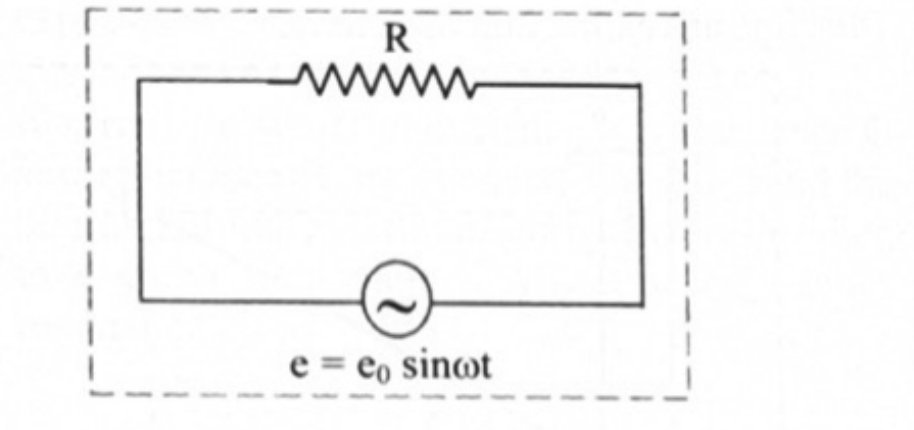
In a pure resistor the alternating current is in phase with the applied alternating voltage: if then .
Instantaneous power:
This varies with time, so the average power over a complete cycle is obtained by integrating (1):
This product is also called the apparent power.
Power factor in a purely resistive circuit: , so .
(b) Average Power Associated with an Inductor
In a purely inductive circuit the current lags the voltage by : if then .
The average power over a complete cycle of AC through an ideal inductor is zero. This is the board's question "when an AC source is connected to an ideal inductor, show that the average power supplied by the source over a complete cycle is zero".
(c) Average Power Associated with a Capacitor
In a purely capacitive circuit the current leads the emf by : if then .
The average power supplied to an ideal capacitor by the source over a complete cycle of AC is also zero — which proves that an ideal capacitor in an AC circuit does not dissipate power.
(d) Average Power in a Series LCR Circuit
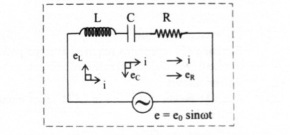
Let be applied across a series combination of a pure inductor, a capacitor and a resistor. There is a phase difference between the applied emf and the current, so
Instantaneous power:
This shows that varies with . Averaging over one cycle,
Now , so the first integral is , and , so the second integral vanishes. Substituting in (2),
This is the average power, or true power, dissipated in the AC circuit. It depends not only on the rms values of current and emf but also on the phase difference between them.
Power Factor
The factor is called the power factor of the circuit.
The average power is the true power, and the product is the apparent power.
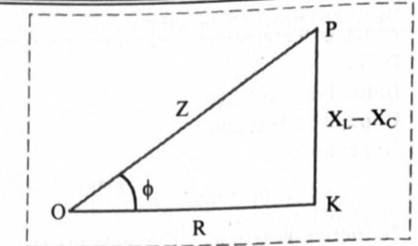
From the impedance triangle,
- Non-inductive circuit (): , so .
- Purely inductive or purely capacitive circuit: , so the power factor is zero and .
Wattless Current
The current through a pure inductor or an ideal capacitor, which consumes no power for its maintenance in the circuit, is called idle current or wattless current. Power is dissipated in a circuit only because of resistance.
Why a Low Power Factor Means Large Transmission Loss
For a given power delivered, , a small forces to be large. The heat wasted in the transmission line is , which rises as the square of that current. Hence circuits used for transporting electric power are kept at a high power factor.
Standard Results
- Pure resistor: ; power factor 1.
- Pure inductor and ideal capacitor: ; power factor 0.
- Series LCR: , .
- Useful integrals: , , .
Worked Pattern
A 100 resistor across a 220 V, 50 Hz supply: A and W (no needed, since it is 1).
A series LCR circuit with , , across V: , so , power factor , and W.
Theory Questions Asked on This Subtopic
Real board questions. Answers are at the end of the page.
- 1
Obtain an expression for average power dissipated in a purely resistive A.C. circuit. Define power factor of the circuit and state its value for purely resistive A.C. circuit.
 Maharashtra HSC board question — asked in October 2015Answer 1 ↓
 - 2
Obtain an expression for average power dissipated in series LCR A.C. circuit. Hence obtain an expression for power factor of the circuit.
 Maharashtra HSC board question — asked in July 2019Answer 2 ↓
 - 3
Derive an expression for the impedance of an LCR circuit connected to an AC power supply. Draw phasor diagram.
 Maharashtra HSC board question — asked in February 2024Answer 3 ↓
Numericals
Every numerical set on this subtopic. Full working is at the end of the page.
- 4
A 100 resistor is connected to a 220 V, 50 Hz supply. Calculate: i. r.m.s. value of current and ii. net power consumed over the full cycle
Maharashtra HSC board question — asked in February 2023Answer 4 ↓
Answers & Solutions
Work the questions above first, then check yourself here. Each answer is set out the way it should be written in the paper.
i. Expression for average power in purely resistive circuit: a. Let, be applied e.m.f across a resistor of resistance 'R' as shown in figure. At certain instant, current is flowing through the resistor. In this case both 'e' and 'i' are in phase. b. Instantaneous power in circuit is given by, c. Average power for a complete cycle can be obtained by integrating equation (1). P is also called as apparent power. ii. Power factor for a circuit is given by, In purely resistive circuit,
i. Expression for average power dissipated in LCR circuit: a. Suppose that an alternating e.m.f is applied across an AC circuit containing L, C and R as shown in figure. b. In such circuit, there is a phase difference between applied emf and current. Therefore, the instantaneous current is given by, . c. Instantaneous power in the circuit is given by, This expression shows that P varies with t. d. Average power dissipated in the circuit can be obtained by integrating equation (1), e. Also, f. Substitute equations (3) and (4) in equation (2), we get, Equation (5) represents required average power or true power dissipated in the AC circuit. ii. Power factor: a. Average power dissipated in LCR series circuit is given by, b. This implies that, the average power dissipated in LCR series circuit depends on the rms values of current and emf as well as the phase difference between them. The term is called power factor. c. It is given by, d. The average power is also termed as true power and product () is called apparent power. e. Consider impedance triangle for series LCR circuit as shown in figure,
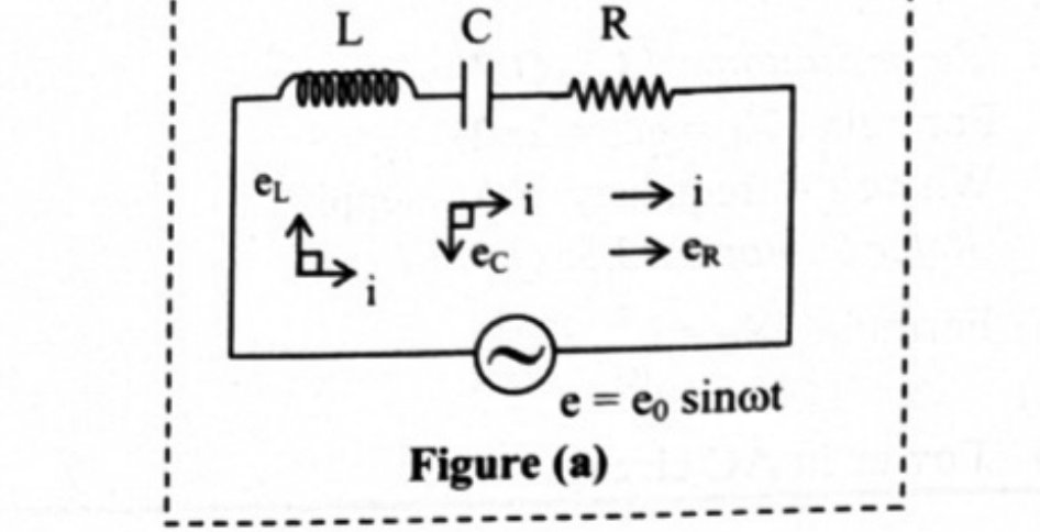
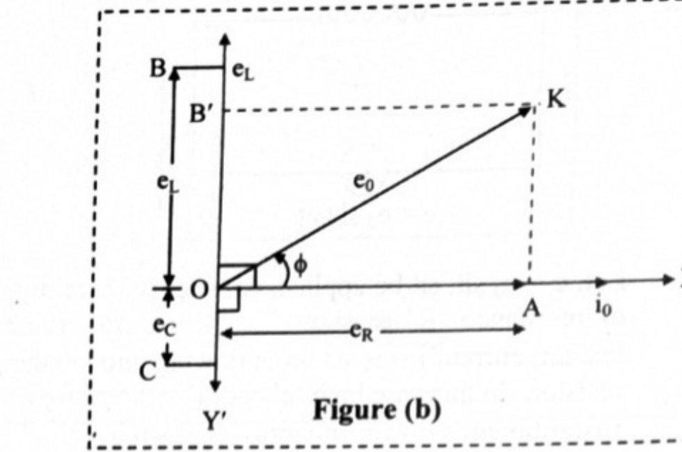
Expression for impedance of AC circuit containing LCR in series: i. Consider an alternating e.m.f applied to a series combination of pure inductor of inductance L, capacitor of capacitance C and resistor of resistance R as shown in figure (a). ii. Let , and be the r.m.s voltage across inductor, capacitor and resistor. As R, L and C are in series, the current at any instant through the three elements has the same amplitude and phase and given as, . iii. As '' is in phase with current i, the vector is drawn in the same direction as that of i along positive direction of X axis. iv. lags the current i by radian (90°), hence the vector '' is drawn in the negative direction of the Y axis along OY'. v. leads the current by radian (90°), hence vector is drawn in the positive direction of Y axis. vi. The voltages through L, C and R are given by , and vii. The voltages across L and C have a phase difference of 180°. Hence, the net reactive voltage is () viii. Consider . The net reactive emf () is in the direction of as shown in figure (b). Resultant of , and gives the r.m.s value (e) of applied e.m.f. which is represented by diagonal OP in figure (b). ix. From the figure (b), From equation (1), where, = Impedance of circuit x. The quantity represents the effective opposition offered by the inductor, capacitor and resistor connected in series to the flow of AC current. This total effective resistance of LCR circuit is called the impedance of the circuit and is represented by Z.
Given: , V, Hz To find: i. rms current () ii. Net power consumed () Formulae: i. ii. Calculation: From formula (i), From formula (ii), W Ans: i. The rms current in the circuit is 2.2 A. ii. Net power consumed over a full cycle is 484 W.