3.13
Wheatstone Bridge
Current Electricity · CBSE
Theory
The circuit, described for the diagram mark
- Four resistors form the four arms of a quadrilateral ABCD: in AB, in BC, in AD and in DC. In CBSE's alternative labelling these are respectively.
- Across one pair of diagonally opposite corners, A and C, a cell (with a key) is connected — this is the battery arm.
- Across the other pair, B and D, a galvanometer G is connected — this is the galvanometer arm.
- Mark the currents: from the cell divides at A into through and through ; a current flows through G from B to D.
Deriving the balance condition
- Of special interest is the balanced bridge, in which the resistances are such that .
- With , the junction rule at B and at D gives immediately that the current through also flows through , and the current through also flows through : call them and .
- Apply the loop rule to the closed loop ABDA. With no current in G there is no potential drop across it, so
- Apply the loop rule to the closed loop BCDB:
- Dividing the first by the second,
- This is the balance condition — the condition for the galvanometer to show zero, or null, deflection.
- The same result follows from the general loop equations without assuming in advance: writing loop ABDA as and loop BCDB as , then putting and dividing, gives .
Why the bridge is used
- Keeping and known in the first two arms and putting the unknown in the fourth arm, vary until the galvanometer reads zero. Then
- The balance condition involves only the four resistances. It does not contain the emf of the cell, its internal resistance, or the resistance or sensitivity of the galvanometer — this is why the null method is accurate and why the bridge is preferred to measuring and separately.
- At balance, B and D are at the same potential, so the galvanometer arm carries no current and may be removed altogether, or replaced by a wire, without changing any current in the rest of the circuit. That is what makes balanced-bridge networks easy to reduce.
- Interchanging the cell and the galvanometer does not disturb the balance.
Metre bridge — the practical form
- A metre bridge is a Wheatstone bridge in which two of the arms are the two parts of a uniform wire exactly one metre long, stretched along a metre scale between two thick copper strips.
- The unknown resistance is in the left gap and a known resistance box in the right gap; a cell with a key is across the whole wire, and a galvanometer runs from the midpoint of the gaps to a sliding jockey that can touch the wire anywhere along its length.
- Since the wire is uniform, the resistances of its two parts are proportional to their lengths. At the null (balance) point, at a distance cm from the left end,
- Measure the length and the diameter of the unknown wire; then its specific resistance (resistivity) is
- Precautions worth a line: keep the jockey pressed only momentarily, take the balance point near the middle of the wire so that the fractional error is least, and use a plug key so that current flows only while a reading is taken.
Worked cases
- Recognising a balanced bridge. Arms , , , , with a resistor across BD. Since and , the bridge is balanced, so no current flows through the arm and it may be dropped. Then and in parallel:
- An unbalanced bridge (NCERT Example 3.7). , , , , galvanometer across BD, 10 V across AC. Mesh BADB: . Mesh BCDB: . Mesh ADCEA: . Solving the three gives .
Standard results
- Balance condition: , i.e. , i.e. .
- At balance and ; the galvanometer arm can be removed or shorted.
- The condition is independent of the cell's emf and of the galvanometer's resistance.
- Metre bridge: ; specific resistance .
- Balanced bridge with a resistor across the galvanometer arm: ignore that resistor and reduce the two branches in parallel.
Theory Questions Asked on This Subtopic
Real board questions. Answers are at the end of the page.
- 1
Use Kirchhoff's rules to obtain the balance condition in a Wheatstone bridge.
- 2
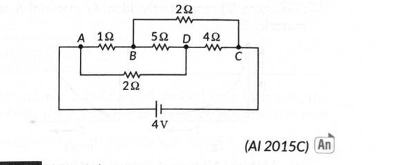
Calculate the current drawn from the battery by the network of resistors shown in the figure.
- 3
Derive an expression for the balance condition of a Wheatstone bridge.
- 4
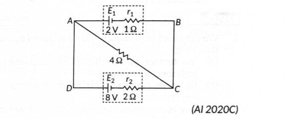
(a) State the principle of working of a Wheatstone bridge. With the help of a circuit diagram, explain how it is used in the determination of the specific resistance of the material of a wire using a metre bridge. (b) A cell of emf V and internal resistance is connected to another cell of emf V and internal resistance through an external resistance of , as shown in the figure. Find the potential difference between point and point .
Answers & Solutions
Work the questions above first, then check yourself here. Each answer is set out the way it should be written in the paper.
Let the bridge arms be (as ), a galvanometer of resistance across , current through it, and battery current split as (through ) and (through ). Loop : ...(i) Loop : ...(ii) At balance, and are at the same potential, i.e. . Substituting in (i) and (ii) and dividing: — the Wheatstone bridge balance condition.
Check for balance: with arms , (the diagonal resistor), (the other diagonal resistor) and : and . Since the condition is satisfied, this is a balanced Wheatstone bridge, so no current flows through the arm , which can be removed for the purpose of finding the equivalent resistance. Resistance of arm . Resistance of arm . These two arms are in parallel between and : Current drawn from the battery: A
(Same derivation as in Q73.) Applying Kirchhoff's rules to loops and and setting the galvanometer current at balance gives:
(a) Principle: If four resistances form the four arms of a quadrilateral, with a galvanometer across one diagonal and a battery across the other, no current flows through the galvanometer when (balanced condition). A metre bridge is a practical Wheatstone bridge in which two arms are the two parts (of resistance and ) of a metre-long uniform wire on either side of a sliding jockey, one arm is the unknown resistance , and the fourth is a known resistance box . At the balance (null-deflection) point, , from which the unknown resistance, and hence the specific resistance (resistivity) of its wire, can be calculated using (with the area and length of the unknown wire). (b) Let be the current flowing (say from to to to ) in the single loop . Applying KVL to loop (through the diagonal) and loop : Loop : ...(i) [ = current through the diagonal, = current through ] Loop : ...(ii) Adding (i) and (ii): A Potential difference between and (across the diagonal): V