3.3
Electric Currents in Conductors
Current Electricity · CBSE
Theory
The free-electron picture
- A charge in an electric field feels a force; if it is free to move it contributes to a current. Free charges exist in nature — for example in the ionosphere — but inside atoms and molecules electrons and nuclei are bound.
- In bulk matter the molecules are packed so closely that in some materials, notably metals, the electrons are no longer attached to individual nuclei and are practically free to move through the whole solid. Such materials are conductors. In others the electrons stay bound and do not accelerate even in a field — insulators.
- In solid conductors the current is carried entirely by the negatively charged electrons against a background of fixed positive ions. In electrolytic solutions both positive and negative ions move.
Without a field, and with one
- With no field applied, the electrons move because of thermal energy. They collide repeatedly with the fixed ions; after a collision an electron emerges with the same speed but in a completely random direction.
- Hence at any instant, on the average, as many electrons travel in one direction as in the opposite direction. The average velocity is zero and there is no net current.
- When a potential difference is applied across the ends, a field is set up inside. Each electron feels , opposite to because its charge is negative.
- This superimposes a small net velocity — the drift velocity — on the random thermal motion, directed opposite to , i.e. towards the positive end. The random motion continues exactly as before; a drift is simply added to it, and that drift is the current.
NCERT's cylinder: why a steady current needs a cell
- Take a conducting cylinder of radius . Attach to its two flat faces two thin dielectric discs carrying and . A field is created, directed from the positive charge to the negative charge, and electrons are accelerated towards .
- While they move they constitute a current — but they are moving so as to neutralise the charges, so after a very short while the charges are gone, the field disappears and the current stops.
- If instead the ends are continuously supplied with fresh charge to make up for what the electrons neutralise, there is a steady field in the body of the conductor and hence a continuous current. Cells and batteries are exactly such mechanisms.
Resistance against resistivity — the 3-mark comparison
| Resistance | Resistivity |
|---|---|
| The obstruction a particular conductor offers to the flow of current, | A property of the material of the conductor alone at a given temperature, |
| Depends on length, area of cross-section, material and temperature | Independent of the length and area of cross-section; depends on the material and temperature |
| Changes when the conductor is cut, stretched or reshaped | Unchanged when the conductor is cut, stretched or reshaped |
| SI unit ohm () | SI unit ohm-metre ( m) |
Ideal meters in a circuit
- An ideal ammeter has zero resistance, so inserting it changes nothing; it is always connected in series.
- An ideal voltmeter has infinite resistance, so it draws no current; it is always connected in parallel and simply reads the potential difference across the branch it spans.
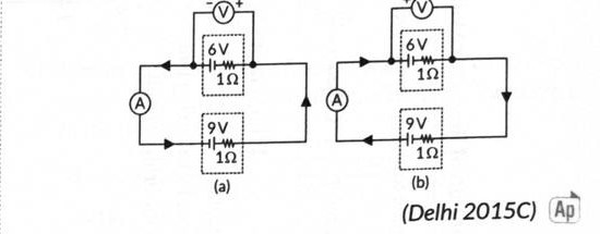
- CBSE's worked circuits: two cells of 6 V and 9 V, each of internal resistance , in a single loop with an ideal ammeter and an ideal voltmeter across the 6 V branch. Total loop resistance in both cases; the voltmeter reads 6 V in both.
- Cells aiding: net emf , so .
- Cells opposing: net emf , so .
Standard results
- No field: average electron velocity zero, no current. With a field: drift superposed on random motion.
- Force on an electron in the conductor, ; drift is opposite to .
- A transient current dies out unless a cell keeps the field steady.
- is of the conductor; is of the material.
- Ideal ammeter: zero resistance, in series. Ideal voltmeter: infinite resistance, in parallel.
Theory Questions Asked on This Subtopic
Real board questions. Answers are at the end of the page.
- 1
How does the random motion of free electrons in a conductor get affected when a potential difference is applied across its ends?
- 2
Differentiate between electrical resistance and resistivity of a conductor.
- 3
In the two electric circuits shown in the figure, determine the readings of the ideal ammeter (A) and the ideal voltmeter (V).
Answers & Solutions
Work the questions above first, then check yourself here. Each answer is set out the way it should be written in the paper.
In the absence of an applied field, the free electrons in a conductor move randomly in all directions (like gas molecules in a container), colliding repeatedly with the lattice ions, so their average velocity — and hence the net current — is zero. When a potential difference is applied across the ends, an electric field is set up inside the conductor. Each electron now experiences a force (opposite to , since the electron's charge is negative). This force superimposes a small net velocity, called the drift velocity , directed opposite to (i.e. towards the positive end), on the electrons' random thermal motion. The random motion itself continues unaffected in direction, but a net drift is added to it, producing a current.
Resistance (): It is the obstruction offered by a specific conductor to the flow of current, . It depends on the length, area of cross-section, material and temperature of the conductor. Its SI unit is ohm (). Resistivity (): It is a property of the material of the conductor alone (at a given temperature), . It does not depend on the length or area of cross-section of the conductor. Its SI unit is ohm-metre ( m).
Since the ammeter is ideal, it has zero resistance; since the voltmeter is ideal, it has infinite resistance and draws no current — it simply reads the potential difference across the 6 V cell branch it is connected across, so the voltmeter reads 6 V in both circuits. The two 1 resistances (the internal resistances of the two cells) are in series around the loop, giving a total resistance of in each case. Circuit (a): the two cells (6 V and 9 V) are connected so as to aid each other around the loop, so the net emf driving the current is V. Ammeter reading (a): A Circuit (b): the two cells oppose each other around the loop, so the net emf is V. Ammeter reading (b): A