16.2
p-n Junction Diode as a Rectifier
Semiconductor Devices · Maharashtra HSC
Theory
Definitions
- An AC voltage varies sinusoidally: both its magnitude and its direction change during one cycle. A rectifier converts this bidirectional voltage or current into a unidirectional voltage or current.
- Rectification: the conversion of AC voltage into DC voltage.
- Rectifier: an electronic circuit which rectifies AC voltage.
- Two types of rectifier circuit: half wave rectifier and full wave rectifier.
16.2.1 Half wave rectifier
Circuit, described in words
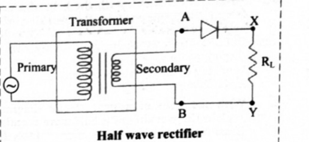
The AC mains is applied to the primary of a transformer. The secondary coil AB is connected in series with a single diode D and the load resistance . Point A of the secondary goes to the anode of D; the cathode of D goes to one end of ; the other end of returns to point B. The output DC voltage is taken across .
The transformer serves two purposes: it lets us step the AC input up or down as the circuit requires, and it isolates the rectifier circuit from the mains supply, reducing the risk of electric shock.
Working
- The AC voltage across the secondary coil AB changes its polarity after every half cycle.
- When the positive half cycle begins, the voltage at the point A is at a higher potential with respect to that at the point B. The diode D is therefore forward biased. It conducts (works as a closed switch) and current flows through the circuit.
- When the negative half cycle begins, the potential at the point A is lower with respect to that at the point B and the diode is reverse biased. It does not conduct (works as an open switch) and no current passes through the circuit.
- Hence the diode conducts only during the positive half cycles of the AC input and blocks the current during the negative half cycles.
- In this way current always flows through the load in the same direction, for alternate positive half cycles. The DC output voltage obtained across is in the form of alternate pulses.
Waveforms, described in words
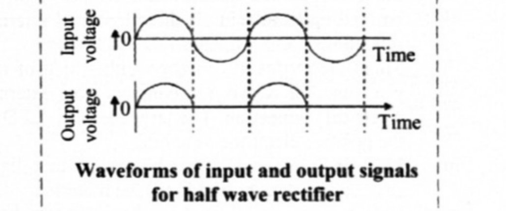
The input waveform is a full sine wave — positive humps and negative humps alternating. The output waveform across keeps only the positive humps; in place of every negative hump there is a flat gap along the time axis. So the output is a train of positive half-sine pulses separated by equal blank intervals.
Ripple frequency
For one AC input cycle we get one cycle of pulsating DC, so
for the standard mains.
16.2.2 Full wave rectifier
The output of a half wave rectifier is available only in alternate positive half cycles; all negative half cycles are lost, so its efficiency is poor. A rectifier using two diodes is more useful. In a full wave rectifier, current flows through the load in the same direction during both half cycles of the input AC, because the circuit contains two diodes conducting alternately.
Circuit, described in words
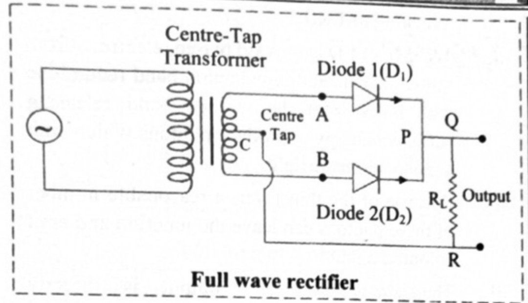
The circuit consists of a centre tapped transformer and two diodes and . The two ends of the secondary are A (top) and B (bottom), and the centre tap C is the common return. A goes to the anode of and B goes to the anode of ; the cathodes of both diodes are joined together at point P, and the load resistance is connected between that junction and the centre tap C, through the points Q and R. The output is taken across .
The diodes are connected such that conducts in the positive half cycle and conducts in the negative half cycle of the input voltage.
Working — the board's five steps
- The full wave rectifier circuit consists of two diodes conducting alternately.
- The circuit consists of a centre tapped transformer and diodes and connected such that conducts in the positive half cycle and conducts in the negative half cycle of the input voltage.
- During the positive half cycle of the input voltage, the point A is at a higher potential than that of the point B and the diode conducts. The current through the load resistance follows the path APQRC.
- During the negative half cycle of the input voltage, point B is at a higher potential than point A and the diode conducts. The current through the load resistance follows the path BPQRC.
- Thus the current flowing through the load resistance is in the same direction during both the cycles, and the DC output voltage obtained across is in the form of continuous pulses.
Waveforms, described in words
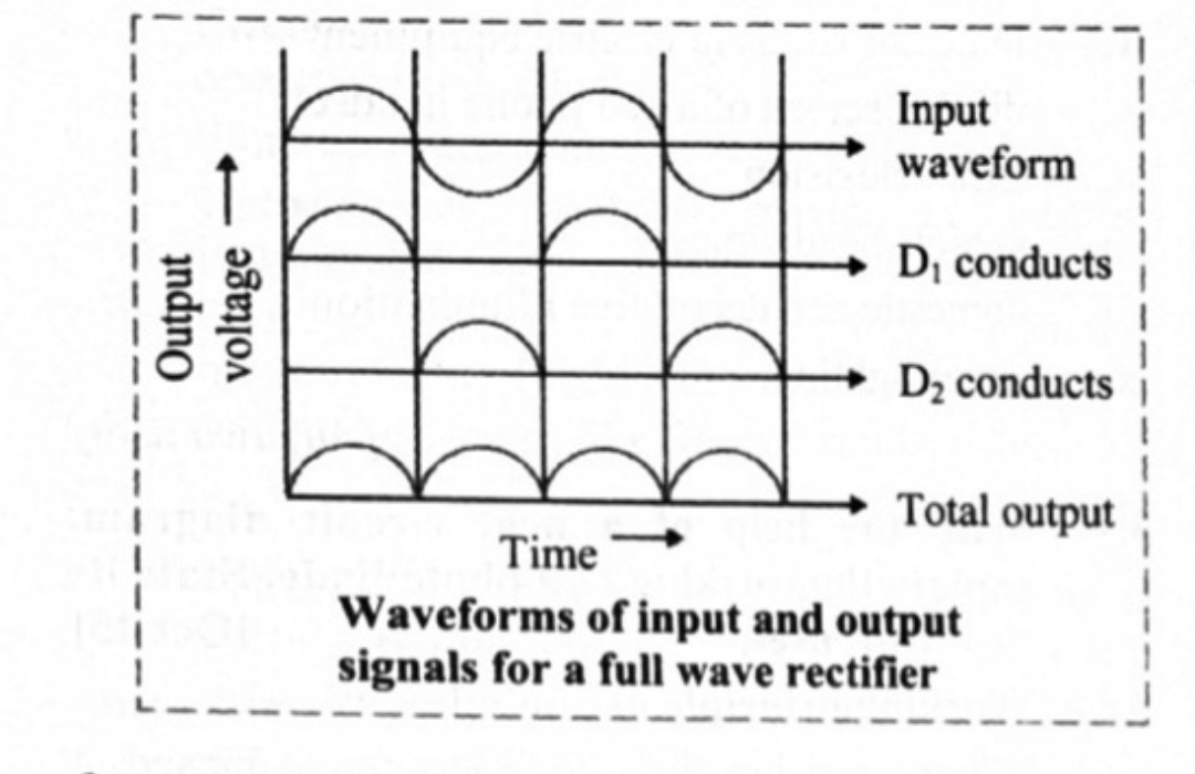
Four waveforms are drawn one below the other. First, the input AC — a full sine wave. Second, the output when conducts — positive humps in the positive half cycles only, with gaps elsewhere. Third, the output when conducts — positive humps in the negative half cycles only, filling exactly the gaps of the second waveform. Fourth, the total output of the full wave rectifier — the two interleaved, giving an unbroken train of positive humps with no gaps at all.
Ripple frequency
For one input AC cycle we get two cycles of pulsating DC, so
for the standard mains.
Advantages of a full wave rectifier
- Rectification takes place in both the cycles of the AC input.
- The ripple in a full wave rectifier is less than that in a half wave rectifier.
Efficiency
The maximum efficiency of a full wave rectifier is and that of a half wave rectifier is — the full wave figure is exactly twice the half wave figure. A full wave rectifier utilises both half cycles of the AC input voltage to produce the DC output.
16.2.3 Ripple factor
- The output of a rectifier consists of a small fraction of an AC component along with the DC. This AC component is called the ripple. It is undesirable and is responsible for the fluctuations in the rectifier output.
- The effectiveness of a rectifier depends on the magnitude of the ripple component in its output. A smaller ripple means the rectifier is more effective.
- Ripple factor is the ratio of the root mean square (rms) value of the AC component to the value of the DC component in the rectifier output:
It is a pure number, with no unit.
16.2.4 Filter circuits
- The rectifier output is unidirectional but not steady: it keeps fluctuating because of the ripple component in it.
- A filter circuit is a circuit which removes the AC component or the ripple from a rectifier output and allows only the DC component through. This is why a power supply needs a filter.
Capacitor filter, working described in words
A capacitor is connected in parallel with the load, across the rectifier output.
- The pulsating DC voltage of the rectifier output is applied across the capacitor.
- As the voltage across the capacitor rises, the capacitor gets charged (to point A on the waveform) and supplies current to the load resistance.
- At the end of the quarter cycle, the capacitor is charged to the peak value of the rectified output voltage.
- The rectifier voltage now begins to decrease, so the capacitor starts discharging through the load resistance and the voltage across it begins to drop.
- The voltage across the load decreases only slightly, up to a point B, because the next voltage peak recharges the capacitor immediately.
- This process is repeated again and again, and the output waveform becomes a nearly flat line with a small saw-tooth ripple riding on top of it.
- This output is unregulated DC; a voltage regulator circuit is needed to obtain a regulated DC supply.
Why the capacitor filter is used
Low cost, small size and light weight. It is preferred for small load currents and is commonly used in battery eliminators.
Regulated and unregulated power supply
- When a power supply is connected to a load, there is usually a drop in the output voltage. A power supply whose output changes when a load is connected across it is called an unregulated power supply.
- When the output of a power supply remains steady even after connecting a load across it, it is called a regulated power supply. A commonly used voltage regulator circuit uses a Zener diode.
Standard results
| Quantity | Half wave | Full wave |
|---|---|---|
| Number of diodes | 1 | 2 |
| Transformer | Ordinary | Centre tapped |
| Output for a 50 Hz input | ||
| Maximum efficiency | ||
| Output shape | Alternate pulses | Continuous pulses |
| Ripple | More | Less |
- Ripple factor .
- Example 16.1: with a input, the output frequency is for a half wave rectifier (one DC cycle per input cycle) and for a full wave rectifier (two DC cycles per input cycle).
Theory Questions Asked on This Subtopic
Real board questions. Answers are at the end of the page.
- 1
With neat circuit diagram, explain p – n junction diode as full wave rectifier. Draw necessary graphs.
 Maharashtra HSC board question — asked in October 2009Answer 1 ↓
 - 2
With the help of neat labelled circuit diagram explain the working of half wave rectifier using semiconductor diode. Draw the input and output waveforms.
 Maharashtra HSC board question — asked in March 2013Answer 2 ↓
 - 3
Explain with a neat diagram, how a p-n junction diode is used as a half wave rectifier.
Maharashtra HSC board question — asked in March 2017Answer 3 ↓ - 4
What is rectifier? With a neat circuit diagram, explain working of P-N junction diode as a full wave rectifier. OR What is a rectifier? With the help of a neat circuit diagram explain the working of a full wave rectifier.
Maharashtra HSC board question — asked in February 2020; October 2008Answer 4 ↓ - 5
What is a rectifier? With the help of a neat circuit diagram, explain the working of a half wave rectifier.
Maharashtra HSC board question — asked in March 2022Answer 5 ↓ - 6
With the help of a neat circuit diagram, explain the working of a half wave rectifier. Draw input-output waveforms.
Maharashtra HSC board question — asked in July 2023Answer 6 ↓
Answers & Solutions
Work the questions above first, then check yourself here. Each answer is set out the way it should be written in the paper.
Working of full wave rectifier: i. The full wave rectifier circuit consists of two diodes conducting alternately as shown in the given circuit diagram. ii. The circuit consists of a centre tapped transformer and diodes and connected such that conducts in the positive half cycle and conducts in the negative half cycle of the input voltage. iii. During the positive half cycle of the input voltage, the point A is at a higher potential than that of the point B and the diode conducts. The current through the load resistance follows the path APQRC as shown in figure. iv. During the negative half cycle of the input voltage, point B is at higher potential than point A and the diode conducts. The current through the load resistance follows the path BPQRC. v. Thus, the current flowing through the load resistance is in the same direction during both the cycles and DC output voltage obtained across in the form of continuous pulses. Input-output waveforms for full-wave rectifier:
Working of half wave rectifier: i. The given figure shows the circuit of a half wave rectifier. ii. The secondary coil AB of a transformer is connected in series with a diode D and the load resistance . The AC voltage across the secondary coil AB changes its polarities after every half cycle. iii. When the positive half cycle begins, the voltage at the point A is at higher potential with respect to that at the point B, therefore, the diode (D) is forward biased. It conducts and current flows through the circuit. iv. When the negative half cycle begins, the potential at the point A is lower with respect to that at the point B and the diode is reverse biased, therefore, it does not conduct and no current passes through the circuit. v. Hence, the diode conducts only in the positive half cycles of the AC input. It blocks the current during the negative half cycles. In this way, current always flows through the load in the same direction for alternate positive half cycles and DC output voltage obtained across in the form of alternate pulses. Input-output waveforms for half-wave rectifier:
[From 16.2, Q2] Working of half wave rectifier: i. The given figure shows the circuit of a half wave rectifier. ii. The secondary coil AB of a transformer is connected in series with a diode D and the load resistance . The AC voltage across the secondary coil AB changes its polarities after every half cycle. iii. When the positive half cycle begins, the voltage at the point A is at higher potential with respect to that at the point B, therefore, the diode (D) is forward biased. It conducts and current flows through the circuit. iv. When the negative half cycle begins, the potential at the point A is lower with respect to that at the point B and the diode is reverse biased, therefore, it does not conduct and no current passes through the circuit. v. Hence, the diode conducts only in the positive half cycles of the AC input. It blocks the current during the negative half cycles. In this way, current always flows through the load in the same direction for alternate positive half cycles and DC output voltage obtained across in the form of alternate pulses. Input-output waveforms for half-wave rectifier:
An electronic circuit which rectifies AC voltage is called rectifier. [From 16.2, Q1] Working of full wave rectifier: i. The full wave rectifier circuit consists of two diodes conducting alternately as shown in the given circuit diagram. ii. The circuit consists of a centre tapped transformer and diodes and connected such that conducts in the positive half cycle and conducts in the negative half cycle of the input voltage. iii. During the positive half cycle of the input voltage, the point A is at a higher potential than that of the point B and the diode conducts. The current through the load resistance follows the path APQRC as shown in figure. iv. During the negative half cycle of the input voltage, point B is at higher potential than point A and the diode conducts. The current through the load resistance follows the path BPQRC. v. Thus, the current flowing through the load resistance is in the same direction during both the cycles and DC output voltage obtained across in the form of continuous pulses. Input-output waveforms for full-wave rectifier:for Working of full wave rectifier.
Definition: [From 16.2, Q4 (Definition only)] An electronic circuit which rectifies AC voltage is called rectifier. [From 16.2, Q1] Working of full wave rectifier: i. The full wave rectifier circuit consists of two diodes conducting alternately as shown in the given circuit diagram. ii. The circuit consists of a centre tapped transformer and diodes and connected such that conducts in the positive half cycle and conducts in the negative half cycle of the input voltage. iii. During the positive half cycle of the input voltage, the point A is at a higher potential than that of the point B and the diode conducts. The current through the load resistance follows the path APQRC as shown in figure. iv. During the negative half cycle of the input voltage, point B is at higher potential than point A and the diode conducts. The current through the load resistance follows the path BPQRC. v. Thus, the current flowing through the load resistance is in the same direction during both the cycles and DC output voltage obtained across in the form of continuous pulses. Input-output waveforms for full-wave rectifier:for Working of full wave rectifier. Working of half wave rectifier: [From 16.2, Q2] Working of half wave rectifier: i. The given figure shows the circuit of a half wave rectifier. ii. The secondary coil AB of a transformer is connected in series with a diode D and the load resistance . The AC voltage across the secondary coil AB changes its polarities after every half cycle. iii. When the positive half cycle begins, the voltage at the point A is at higher potential with respect to that at the point B, therefore, the diode (D) is forward biased. It conducts and current flows through the circuit. iv. When the negative half cycle begins, the potential at the point A is lower with respect to that at the point B and the diode is reverse biased, therefore, it does not conduct and no current passes through the circuit. v. Hence, the diode conducts only in the positive half cycles of the AC input. It blocks the current during the negative half cycles. In this way, current always flows through the load in the same direction for alternate positive half cycles and DC output voltage obtained across in the form of alternate pulses. Input-output waveforms for half-wave rectifier:
[From 16.2, Q2] Working of half wave rectifier: i. The given figure shows the circuit of a half wave rectifier. ii. The secondary coil AB of a transformer is connected in series with a diode D and the load resistance . The AC voltage across the secondary coil AB changes its polarities after every half cycle. iii. When the positive half cycle begins, the voltage at the point A is at higher potential with respect to that at the point B, therefore, the diode (D) is forward biased. It conducts and current flows through the circuit. iv. When the negative half cycle begins, the potential at the point A is lower with respect to that at the point B and the diode is reverse biased, therefore, it does not conduct and no current passes through the circuit. v. Hence, the diode conducts only in the positive half cycles of the AC input. It blocks the current during the negative half cycles. In this way, current always flows through the load in the same direction for alternate positive half cycles and DC output voltage obtained across in the form of alternate pulses. Input-output waveforms for half-wave rectifier: