16.5
Logic gates
Semiconductor Devices · Maharashtra HSC
Theory
Analog and digital signals
- A continuously varying signal (voltage or current) is called an analog signal; a sinusoidal voltage is the standard example. In an analog electronic circuit the output signal varies continuously according to the input signal.
- A signal (voltage or current) which can have only two discrete values is called a digital signal; a square wave is the standard example. In a digital circuit the output voltage can have only two states: low () or high ().
- An electronic circuit that handles only a digital signal is called a digital circuit, and the branch of electronics dealing with digital circuits is digital electronics.
Logic gate, truth table, Boolean expression
- Logic gate: a digital circuit with one or more input signals but only one output signal, which follows a certain logical relationship between the input and output voltages. They are called gates because they control the flow of signal or information. The output of a logic gate can be in only one of two states — high voltage or low voltage — and which one it is depends on the condition at its inputs.
- Truth table: a table showing all possible combinations of the inputs and the corresponding outputs. The truth table defines the function of a logic gate, and any logic gate can be analysed by constructing one.
- Boolean expression: the mathematical statement that provides the relationship between the input and the output of a logic gate.
- The five common logic gates are the NOT gate, the AND gate, the OR gate, the NAND gate and the NOR gate. Each is indicated by a symbol and its function is defined by a truth table. The Exclusive-OR gate is also studied.
- Uses of logic gates: they make logical decisions in digital circuits, and combinations of them build every digital system — counters, adders, memories, calculators and computers.
16.5.1 NOT gate
This is the most basic logic gate. It has one input and one output. It produces a high output, output , if the input is ; when the input is high or , its output is low or . That is, it produces a negated version of the input at its output. This is why it is also known as an inverter.
Symbol in words: a small triangle pointing to the right with a small circle (bubble) at its tip; the input enters at the flat back of the triangle and the output leaves from the bubble.
Boolean equation:
| Input X | Output Y |
|---|---|
| 0 | 1 |
| 1 | 0 |
It is the only gate with a single input and a single output.
16.5.2 OR gate
An OR gate has two or more inputs and one output. It is also called logical addition. The output is or high when either input A or input B or both are — that is, if any one input is high, or both are high, the output is high.
Symbol in words: a curved shield shape, concave on the input side where the two input lines enter, and drawn out to a point on the right where the single output leaves.
Boolean expression:
| Input A | Input B | Output Y |
|---|---|---|
| 0 | 0 | 0 |
| 0 | 1 | 1 |
| 1 | 0 | 1 |
| 1 | 1 | 1 |
The OR gate is the gate which generates a high output when at least one input is high.
16.5.3 AND gate
An AND gate has two or more inputs and one output. The AND operation represents logical multiplication. The output of an AND gate is high or only when input A and input B are both , or both high, simultaneously.
Symbol in words: a D-shape — flat on the left where the two inputs enter, semicircular on the right where the single output leaves.
Boolean expression:
| Input A | Input B | Output Y |
|---|---|---|
| 0 | 0 | 0 |
| 0 | 1 | 0 |
| 1 | 0 | 0 |
| 1 | 1 | 1 |
16.5.4 NAND gate
The NAND gate is formed by connecting the output of an AND gate to the input of a NOT gate, so its output is exactly the opposite of that of an AND gate. If the inputs A and B are both high, or , the output is the negation, that is low or . The gate derives its name from this NOT-AND behaviour.
Symbol in words: the AND gate D-shape with a small circle (bubble) added at its output.
Boolean expression:
| Input A | Input B | Output Y |
|---|---|---|
| 0 | 0 | 1 |
| 0 | 1 | 1 |
| 1 | 0 | 1 |
| 1 | 1 | 0 |
16.5.5 NOR gate
The NOR gate is formed by connecting the output of an OR gate to the input of a NOT gate, so its output is exactly the opposite of that of an OR gate. The output of a NOR gate is high or only when both the inputs are low or .
Symbol in words: the OR gate shield shape with a small circle (bubble) added at its output.
Boolean expression:
| Input A | Input B | Output Y |
|---|---|---|
| 0 | 0 | 1 |
| 0 | 1 | 0 |
| 1 | 0 | 0 |
| 1 | 1 | 0 |
Universal gates
The NAND gate and the NOR gate are called universal gates, because any gate can be implemented by a combination of NAND gates alone or of NOR gates alone.
16.5.6 Exclusive-OR (X-OR) gate
The Exclusive-OR logic function is a very useful circuit used in many kinds of computational circuits. Its ability to compare two logic levels and produce an output that depends on the input condition is valuable in computational logic.
The output of an Exclusive-OR gate goes high only when its two input terminals are at different logic levels with respect to each other. Put another way, an odd number of highs, or s, at its input gives a high, or , at the output. The output is high when either of the inputs A or B is high, but not when both A and B are high.
Symbol in words: the OR gate shield shape with one extra curved line drawn just outside and parallel to the concave input edge.
Boolean expression:
| Input A | Input B | Output C |
|---|---|---|
| 0 | 0 | 0 |
| 0 | 1 | 1 |
| 1 | 0 | 1 |
| 1 | 1 | 0 |
All gates in one table
| A | B | AND | OR | NAND | NOR | X-OR |
|---|---|---|---|---|---|---|
| 0 | 0 | 0 | 0 | 1 | 1 | 0 |
| 0 | 1 | 0 | 1 | 1 | 0 | 1 |
| 1 | 0 | 0 | 1 | 1 | 0 | 1 |
| 1 | 1 | 1 | 1 | 0 | 0 | 0 |
Standard results
- NOT: ; single input, single output; also called an inverter.
- OR: ; logical addition; high when at least one input is high.
- AND: ; logical multiplication; high only when both inputs are high.
- NAND: ; the complement of AND; low only when both inputs are high.
- NOR: ; the complement of OR; high only when both inputs are low.
- X-OR: ; high only when the inputs differ.
- NAND and NOR are the universal gates.
Theory Questions Asked on This Subtopic
Real board questions. Answers are at the end of the page.
- 1
Draw the logical symbol of NAND gate and give truth table of NAND gate.
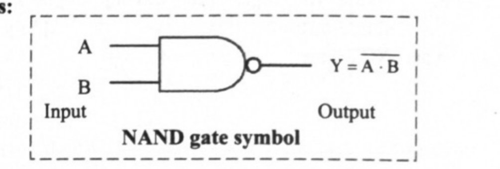 Maharashtra HSC board question — asked in March 2008Answer 1 ↓
 - 2
Draw the schematic symbols for AND, OR, NOT and NAND gate.
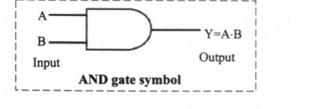
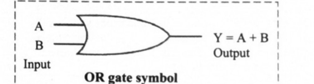
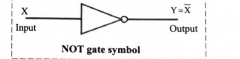 Maharashtra HSC board question — asked in July 2016Answer 2 ↓
 - 3
Name the logic gate which generates high output when at least one input is high.
Maharashtra HSC board question — asked in March 2019Answer 3 ↓ - 4
Write the Boolean expression for Exclusive – OR (X – OR) gate.
Maharashtra HSC board question — asked in March 2022Answer 4 ↓ - 5
Name the logic gate having single input-single-output.
Maharashtra HSC board question — asked in July 2023Answer 5 ↓
Answers & Solutions
Work the questions above first, then check yourself here. Each answer is set out the way it should be written in the paper.
Truth table:
Input A Input B Output Y 0 0 1 0 1 1 1 0 1 1 1 0 i. AND gate: ii. OR gate: iii. NOT gate: iv. NAND gate: [From 16.5, Q1]
Truth table:
Input A Input B Output Y 0 0 1 0 1 1 1 0 1 1 1 0 for symbol OR gate generates high output when at least one input is high.
Boolean expression for X-OR gate:
NOT Gate