12.5
Motional Electromotive Force
Electromagnetic Induction · Maharashtra HSC
Theory
(a) Translational motion of a conductor
Set-up and diagram
- Consider a C-shaped frame of wires PQRS of area situated in a constant magnetic field . QR is a conducting wire of length that slides on the frame, parallel to PS.
- Diagram in words: a rectangular circuit lying in the plane of the paper with into the page (crosses drawn all over); the left arm PS is fixed, the right arm QR is a sliding bar of length ; the bar moves to the right with velocity along the -axis, so the enclosed length is and the area is .
Derivation from the flux rule
- As the wire QR of length is moved out with velocity to increase , the area of the loop PQRS increases, so the flux of through the loop increases with time.
- According to the flux rule, the induced emf equals the rate at which the magnetic flux through the conducting circuit changes. The induced emf will cause a current in the loop; it is assumed that there is enough resistance in the wire so that the induced currents are very small and produce a negligible magnetic field of their own.
- As the flux through the frame PQRS is , the magnitude of the induced emf is
- where is the velocity of the wire QR increasing the length of the wires PQ and SR.
The same result from the Lorentz force
- A charge carried along by the moving wire QR experiences the Lorentz force
- which is perpendicular to both and and hence is parallel to the wire QR.
- The force is constant along the length of the wire QR (since and are constant) and zero elsewhere, because for the stationary part RSPQ of the frame.
- When the charge moves a distance along the wire, the work done by the Lorentz force is
- where is the angle between and .
- The emf generated is work per unit charge:
- For maximum induced emf, :
- Equations (1) and (2) agree. In general it can be proved that for any circuit whose parts move in a fixed magnetic field, the induced emf is the time derivative of the flux, regardless of the shape of the circuit.
The stationary-loop case
- The flux rule also applies to a wire loop kept stationary while the magnetic field is changed. The Lorentz force on the charges is ; there are no new special forces due to changing magnetic fields, and any force on charges at rest in a stationary wire must come from the term.
- Faraday's observations therefore led to a new law relating electric and magnetic fields: in a region where the magnetic field is changing with time, electric fields are generated. It is this electric field that drives the electrons around the circuit and is responsible for the induced emf in a stationary circuit whenever the flux changes.
- The flux rule holds good so long as the change in flux is due to a change of magnetic field, or to the motion of the circuit, or both.
(b) Motional emf in a rotating bar
Set-up and diagram
- A conducting bar of length rotates about a pivot at one end, in a plane perpendicular to a uniform magnetic field , with angular velocity . A rotational emf is induced between the two ends of the bar.
- Diagram in words: a straight rod pivoted at O, sweeping out a circle in the plane of the page, with into the page; a small element of the rod is marked at a distance from the pivot.
- A rotating bar differs from a sliding bar because different points of it move with different speeds: the element at distance has .
Derivation
- Consider a small segment of the bar at distance from the pivot. It is a short length of conductor moving with velocity in the field , so it has an induced emf like a sliding bar:
- All such segments are in series, so the emfs of the individual segments add. The total induced emf in the rotating rod is
- Compare this with the induced emf in the sliding bar, : the rotating bar carries the extra factor .
- With , where is the number of revolutions per second, this can be written as
Faraday disc dynamo
- The same argument applied to a metal disc of radius rotating with angular velocity about an axis through its centre and perpendicular to its plane, in a field parallel to that axis, gives the emf between the rim and the axis:
- Read as flux cut: a radius of the disc sweeps out an area per second, and the flux cut per second is , which is numerically the induced emf.
Standard results
- Sliding bar, , , mutually perpendicular: .
- General orientation: with the angle between and ; when is parallel to .
- Rotating rod about one end: .
- Faraday disc: ; area swept per second by a radius ; flux cut per second .
- Aircraft wings, railway axles and falling wires are all problems, using the component of the earth's field perpendicular to both and .
Theory Questions Asked on This Subtopic
Real board questions. Answers are at the end of the page.
- 1
Derive an expression for emf (e) generated in a conductor of length (l) moving in uniform magnetic field (B) with uniform velocity (v) along x-axis.
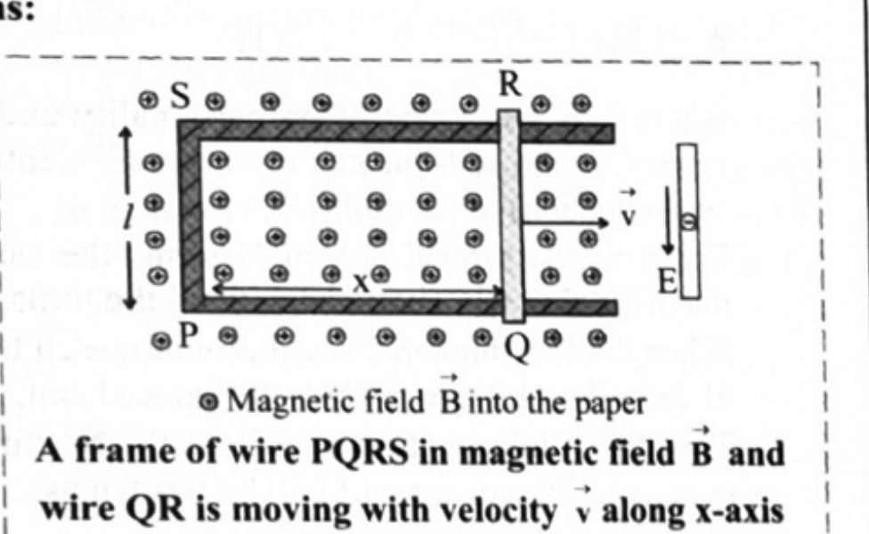 Maharashtra HSC board question — asked in March 2022Answer 1 ↓
Numericals
Every numerical set on this subtopic. Full working is at the end of the page.
- 2
A metal rod m long rotates about one of its ends perpendicular to a plane whose magnetic induction is T. Calculate the number of revolutions made by the rod per second if the e.m.f. induced between the ends of the rod is 16 mV.
Maharashtra HSC board question — asked in March 2014Answer 2 ↓ - 3
An aircraft of wing span of 50 m flies horizontally in earth's magnetic field of T. Calculate the velocity required to generate an e.m.f. of 1.2 V between the tips of the wings of the aircraft.
Maharashtra HSC board question — asked in July 2022Answer 3 ↓ - 4
A wire 5 m long is supported horizontally at a height of 15 m along east-west direction. When it is about to hit the ground, calculate the average e.m.f. induced in it. (g = 10 m/s²)
Maharashtra HSC board question — asked in February 2023Answer 4 ↓ - 5
An aircraft of wing span of 60 m flies horizontally in earth's magnetic field of T at a speed of 500 m/s. Calculate the e.m.f. induced between the tips of wings of aircraft.
Maharashtra HSC board question — asked in February 2024Answer 5 ↓
Answers & Solutions
Work the questions above first, then check yourself here. Each answer is set out the way it should be written in the paper.
i. Consider a C shaped frame of wires PQRS of area (lx) situated in a constant magnetic field . Here, QR is a conducting wire that slides on the frame parallel to PS. ii. As the wire QR of length l is moved out with velocity to increase x, the area of the loop PQRS increases. Thus the flux of through the loop increases with time. iii. According to the flux rule, the induced emf will be equal to the rate at which the magnetic flux through a conducting circuit changes. iv. The induced emf will cause a current in the loop. It is assumed that there is enough resistance in the wire so that the induced currents are very small producing negligible magnetic field. v. As the flux through the frame PQRS is Blx, magnitude of the induced emf can be written as where v is the velocity of wire QR increasing the length x of wires PQ and SR. vi. Now, a charge q which is carried along by the moving wire QR, experiences Lorentz force ; which is perpendicular to both and and hence is parallel to wire QR. vii. The force is constant along the length l of the wire QR (as v and B are constant) and zero elsewhere ( v = 0 for stationary part RSPQ of wire frame). viii. When the charge q moves a distance l along the wire, the work done by the Lorentz force is where = angle between and . ix. The emf generated is, x. For maximum induced emf, xi. Thus, from equation (1) and (2), for any circuit whose parts move in a fixed magnetic field, the induced emf is the time derivative of flux () regardless of the shape of the circuit.
Given: m, T, mV V To find: Number of revolutions (f) Formula: Calculation: From formula, Ans: The number of revolutions made by rod per second is 4.
Given: m, T, V To find: Velocity (v) Formula: Calculation: From formula Ans: The velocity required is 400 m/s.
Induced e.m.f. is given by formula, In given condition, the wire initially supported in east-west direction, when falls towards the ground travels in north-south direction. Hence, velocity is acting in the north-south direction. Earth's magnetism also acts from the north pole to the south pole. This makes . Ans: The average induced e.m.f. in the wire will be zero.
Given: m, T, m/s To find: Induced emf (e) Formula: Calculation: From formula Ans: Induced emf between tips of wings is 1.8 V.