3.10
Cells, Emf, Internal Resistance
Current Electricity · CBSE
Theory
The cell, and what emf means
- A cell has two electrodes, the positive P and the negative N, immersed in an electrolytic solution. Dipped in the solution, the electrodes exchange charges with the electrolyte.
- The positive electrode acquires a potential difference with respect to the electrolyte immediately next to it (point A), and the negative electrode a potential with respect to the electrolyte next to it (point B), with .
- When no current flows, the electrolyte is all at one potential, so the potential difference between P and N is . This is the electromotive force (emf) of the cell:
- Emf is a potential difference, not a force; the name survives from a time when the phenomenon was not understood. Equivalently: the emf of a source is the work done per unit charge by the source in carrying charge from its lower-potential terminal to its higher-potential one.
- Definition to write for a mark: emf is the potential difference between the terminals of a cell in an open circuit, i.e. when no current is being drawn from it. Unit: volt.
Internal resistance and the terminal voltage
- The electrolyte through which the current flows has a finite resistance , called the internal resistance of the cell.
- With infinite, no current flows, and going from P through A and B to N gives : the emf is the open-circuit terminal potential difference.
- With finite a current flows, and the potential difference between P and N becomes
- The minus sign appears because inside the cell the current flows from B to A, i.e. against the fall of potential. The terminal voltage is therefore always less than the emf while the cell is discharging.
- Internal resistances may be neglected in practical calculations whenever . Dry cells have much higher internal resistances than ordinary electrolytic cells.
- When the cell is being charged, the external source drives current into the positive terminal, the sign of reverses, and
The circuit relation
- is also the potential difference across the external resistance, so . Combining with :
- The maximum current is drawn when : . In most cells the maximum permitted current is far lower than this, to avoid permanent damage.
- Internal resistance from measurements: , or in terms of the external resistance, .
- Inside the cell the current flows from the negative terminal to the positive terminal; outside, from the positive terminal to the negative terminal through the external circuit.
Emf against terminal voltage — the 2-mark table
| Emf | Terminal potential difference |
|---|---|
| Measured on open circuit, no current drawn | Measured on closed circuit, current flowing |
| Depends only on the nature of the electrodes and the electrolyte | Depends in addition on and on the external resistance |
| Constant for a given cell | Falls as more current is drawn |
| while discharging, while charging | |
| Is the cause | Is the effect |
The two graphs, and how to get and from them
- against . Write and compare with : it is a straight line with intercept on the -axis and slope . It meets the -axis at .
- Hence the -intercept of the line gives the emf of the cell, and the magnitude of its slope gives the internal resistance. That is the whole answer to "how can and be determined from the plot".
- Worked reading: a line falling from at through at has slope , so and .
- against . Write : the curve starts at when , rises steeply at first, then flattens and approaches asymptotically as becomes very large. It never actually reaches .
- The current is largest at and falls monotonically as increases.
Worked cases CBSE has set
- Emf and from two readings. gives , so . gives , so , giving and .
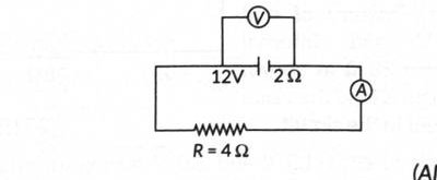
- Ammeter and voltmeter readings. A 12 V source of internal resistance across : (ammeter), and the terminal voltage (voltmeter).
- Charging a battery. An 8 V battery of internal resistance charged from a 120 V dc supply through a series resistor of : the net driving emf is , the total resistance , so , and the terminal voltage of the battery is . The series resistor is there to limit the charging current to a safe value — without it the battery's very low internal resistance would let a dangerously large current flow.
- Drawing a large current safely. Since , a low-voltage battery must have a very low internal resistance to deliver a large current, whereas a high-voltage battery can afford a comparatively larger internal resistance and still supply the same current.
Standard results
- ; (discharging), (charging).
- , , at .
- .
- against : straight line, intercept , slope . against : rising curve, asymptote .
- Current runs N to P inside the cell, P to N outside it.
Theory Questions Asked on This Subtopic
Real board questions. Answers are at the end of the page.
- 1
A cell of emf '' and internal resistance '' is connected across a variable external resistor ''. Plot the variation of the voltage drop '' across the resistor as a function of ''.
- 2
The plot of the variation of potential difference across a combination of three identical cells in series, versus current, is shown in the figure. What is the emf and internal resistance of each cell? [Graph: straight line from V at to at A.]
- 3
A cell of emf and internal resistance is connected to a variable resistance . Draw plots showing the variation of (a) terminal voltage with , and (b) with current , in the circuit.
- 4
Two conductors, made of the same material, have equal lengths but different cross-sectional areas and (). They are connected in parallel across a cell. Show that the drift velocities of electrons in the two conductors are equal.
- 5
A cell of emf '' and internal resistance '' is connected across a variable resistor ''. Plot a graph showing the variation of terminal voltage '' of the cell versus the current ''. Using the plot, show how the emf of the cell and its internal resistance can be determined.
- 6
(a) Distinguish between emf () and terminal voltage () of a cell having internal resistance ''. (b) Draw a plot showing the variation of terminal voltage () vs the current () drawn from the cell.
- 7
A graph is plotted showing the variation of terminal potential difference of a cell as a function of the current drawn from it. Using this plot, how does one determine the internal resistance of the cell?
- 8
(a) The potential difference applied across a given resistor is altered so that the heat produced per second increases by a factor of 9. By what factor does the applied potential difference change? (b) In the figure shown, an ammeter and a resistor of are connected to the terminals of a source of emf 12 V having an internal resistance of . Calculate the voltmeter and ammeter readings.
- 9
(i) A cell of emf '' and internal resistance '' is connected across a variable load resistor . Draw the plots of the terminal voltage versus (i) and (ii) the current . (ii) It is found that when , the current is 1 A, and when is increased to , the current reduces to 0.5 A. Find the values of the emf and internal resistance .
- 10
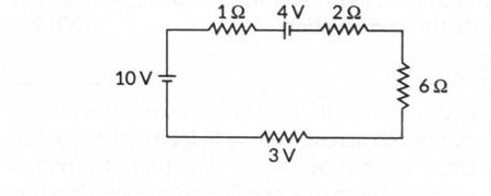
(i) Define electrical conductivity of a wire. Give its SI unit. (ii) High current is to be drawn safely from (1) a low-voltage battery, and (2) a high-voltage battery. What can you say about the internal resistance of the two batteries? (iii) Calculate the total energy supplied by the batteries to the circuit shown in the figure, in one minute.
Numericals
Every numerical set on this subtopic. Full working is at the end of the page.
- 11
In a dc circuit the direction of current inside the battery and outside the battery, respectively, are
- (a)
positive to negative terminal, and negative to positive terminal
- (b)
negative to positive terminal, and positive to negative terminal
- (c)
positive to negative terminal, and positive to negative terminal
- (d)
negative to positive terminal, and negative to positive terminal
- (a)
- 12
A cell of internal resistance connected across an external resistance can supply maximum current when
- (a)
- (b)
- (c)
- (d)
- (a)
Answers & Solutions
Work the questions above first, then check yourself here. Each answer is set out the way it should be written in the paper.
. The graph is a curve starting at when , rising steeply at first and then flattening out, approaching asymptotically as becomes very large.
For the series combination: -intercept V total emf V (emf of each cell). Magnitude of slope total internal resistance (internal resistance of each cell).
(a) : a curve rising from at and approaching asymptotically as . (b) : a straight line with -intercept (at ) and negative slope of magnitude , reaching at .
Since the conductors are in parallel across the same cell, the potential difference across each is the same. , Since neither expression depends on the area, .
: a straight line of negative slope, meeting the -axis at (when ) and the -axis at (when ). The -intercept of the line directly gives the emf of the cell. The magnitude of the slope of the line gives the internal resistance of the cell.
(a) Electromotive force (emf, ) is the potential difference between the terminals of a cell in an open circuit, i.e. when no current is drawn from it. Terminal voltage () is the potential difference between the terminals of a cell in a closed circuit, i.e. when current flows: , so while the cell is discharging. (b) : a straight line with -intercept and negative slope of magnitude .
, which, compared with the straight-line equation (with , ), gives slope and intercept . So the graph is a straight line of negative slope; the magnitude of this slope, read off the graph, gives the internal resistance of the cell (and the -intercept gives its emf ).
(a) . If increases by a factor of 9, then increases by a factor of 9, so increases by a factor of . (b) A (ammeter reading). Voltmeter reading (terminal voltage) V
(i) vs : a curve rising from 0, asymptotically approaching . vs : a straight line, -intercept , slope . (ii) When , A: ...(i) When , A: Substituting from (i): V
(i) Electrical conductivity, (since and ). SI unit: (or S m). (ii) Since , drawing a large current safely requires the total resistance to be small enough relative to : a low-voltage battery must have a very low internal resistance to still deliver a high current, whereas a high-voltage battery can have a comparatively higher internal resistance and still supply the same high current. (iii) For the given circuit, the total (loop) resistance works out to and the net driving emf (10 V cell opposed by the 4 V cell) is V. Current, A Energy supplied by the 10 V battery in 1 minute (60 s): J Energy supplied by the 4 V battery in 1 minute: J Total energy supplied J
Inside the battery, the current flows from the negative to the positive terminal (driven by the emf); outside the battery, it flows from the positive to the negative terminal through the external circuit.
Answer: (d) is maximum when (short circuit), giving .