14.7
Application of Junction Diode as a Rectifier
Semiconductor Electronics · CBSE
Theory
The property that makes rectification possible
- The V-I characteristic shows that a junction diode passes an appreciable current only when it is forward biased, and blocks current almost completely when reverse biased. Its forward resistance is low and its reverse resistance very high.
- So if an alternating voltage is applied across a diode, current flows only during that part of each cycle in which the diode is forward biased. The output is therefore restricted to one direction — it has been rectified.
- Rectifier: the circuit that uses this property to convert an alternating voltage into a unidirectional (pulsating dc) voltage. State the property in exactly these terms whenever CBSE asks "which property of a junction diode makes it suitable for rectification"; the answer is its one-way (unidirectional) conduction.
Half-wave rectifier
Circuit, described in words
- The ac mains is connected to the primary of a step-down transformer. The secondary supplies the desired ac voltage across its two terminals A and B.
- Terminal A is connected through the diode to one end (X) of the load resistor ; terminal B is connected directly to the other end (Y) of . The output voltage is taken across .
- One diode only, and an ordinary (not centre-tapped) secondary.
Working
- Positive half cycle: A is positive and B negative. The diode is forward biased and conducts, so a current flows from A through and through to B. An output voltage appears across .
- Negative half cycle: A is negative and B positive. is now reverse biased and does not conduct, so there is no current and the output across is zero. (The reverse saturation current is negligible and may be taken as zero for practical purposes.)
- In the next positive half cycle the output appears again. Current through therefore flows only during alternate half cycles and always in the same direction, A to B — the output is unidirectional and is said to be rectified.
- Because the output exists for only half of each input wave, this is called a half-wave rectifier.
Waveforms
- Input : a full sine wave with alternating positive and negative humps.
- Output : only the positive humps of that sine wave, each followed by a flat zero stretch lasting one half cycle.
- One output pulse per input cycle, so the output frequency equals the input frequency: a Hz input gives a Hz output, a Hz input gives a Hz output.
Design note
- The reverse breakdown voltage of the diode must be comfortably higher than the peak ac voltage at the transformer secondary, or the diode will break down during the blocked half cycles.
Full-wave rectifier (centre-tap type)
Circuit, described in words
- A step-down transformer whose secondary is centre-tapped: a connection is brought out from the middle of the secondary winding, so the two halves each supply half the total secondary voltage.
- The two ends A and B of the secondary are connected to the p-sides of two diodes and respectively. The n-sides of both diodes are joined together at a common point X.
- The load resistor is connected between this common point X and the centre tap Y, and the output is taken across .
- Two diodes and a centre-tapped secondary. Note that the voltage rectified by each diode is only half the total secondary voltage.
Working
- Positive half cycle: the voltage at A with respect to the centre tap is positive, so the voltage at B, being out of phase, is negative. is forward biased and conducts while is reverse biased and does not. Current flows through , then through from X to Y.
- Negative half cycle: A becomes negative with respect to the centre tap and B becomes positive. Now is reverse biased and does not conduct while is forward biased and does. Current flows through and again through from X to Y.
- Each diode rectifies for only half the cycle, but the two do so for alternate half cycles, and in both halves the current through the load runs in the same direction. So an output is obtained during both the positive and the negative half of every input cycle — a full-wave rectifier, and a more efficient way of getting a rectified voltage than the half-wave circuit.
Waveforms
- Input : a full sine wave. (If the input to A with respect to the centre tap is drawn, the input to B is the same wave inverted, and both are usually drawn one under the other to show they are out of phase.)
- Output : a continuous train of positive humps, one for every half cycle of the input, with no flat gaps between them.
- Two output pulses per input cycle, so the ripple frequency is double the input frequency: Hz in gives Hz out; Hz in gives Hz out. This is the standard "how do you double the frequency of the pulsating output" answer.
The other full-wave circuit
- There is a second full-wave circuit that does not need a centre-tapped transformer but uses four diodes (the bridge rectifier). NCERT mentions it in a bracket and asks nothing more about it; if a question specifies two diodes, draw the centre-tap circuit.
Half-wave versus full-wave
| Feature | Half-wave rectifier | Full-wave rectifier (centre-tap) |
|---|---|---|
| Number of diodes | one | two |
| Transformer secondary | ordinary | centre-tapped |
| Conducting diode | the one diode, in alternate half cycles | in one half cycle, in the other |
| Input used | one half of each cycle | both halves of each cycle |
| Output pulses per input cycle | one | two |
| Output frequency for input | ||
| Output for Hz input | Hz | Hz |
| Gaps in the output | a flat zero half cycle after every pulse | none |
| Efficiency and ease of smoothing | lower | higher |
Filtering: getting steady dc from pulsating dc
- The rectified voltage is a series of half-sinusoidal pulses. It is unidirectional but it does not have a steady value, so it is not yet usable as a dc supply.
- The usual remedy is a capacitor connected across the output terminals, in parallel with the load . An inductor in series with serves the same purpose. Since such circuits filter out the ac ripple and leave a nearly pure dc voltage, they are called filters.
- How the capacitor works: while the rectified voltage is rising, the capacitor charges. With no external load it would simply stay charged to the peak of the rectified output. With a load connected, it discharges through the load between peaks and the voltage across it begins to fall; in the next half cycle of the rectified output it charges back up to the peak.
- The rate of fall of the voltage across the capacitor depends inversely on the product of the capacitance and the effective load resistance — the time constant . A large time constant means the capacitor barely discharges between peaks, so the ripple is small and the output stays close to the peak value of the rectified voltage.
- To make large, must be large — which is why capacitor-input filters use large capacitors. This type of filter is the one most widely used in power supplies.
- Waveform in words: the rectified humps with their tops joined by a nearly flat line that sags slightly between consecutive peaks, the sag being the ripple.
Numerical patterns
- Output frequency: half-wave, ; full-wave, . Standard values: Hz input gives Hz (half-wave) and Hz (full-wave); a Hz input gives Hz (half-wave).
- Reason to write with the number: one output pulse per input cycle in a half-wave rectifier, two in a full-wave rectifier.
Related items CBSE attaches to this section
- "Why is carbon an insulator but silicon a semiconductor, given the same lattice structure?" Both have four valence electrons and the same diamond lattice, but carbon's bonding electrons occupy the second orbit and silicon's the third. Carbon's are held far more tightly, so its band gap ( eV) is much larger than silicon's ( eV) and essentially no electrons are freed at ordinary temperatures — carbon is an insulator. Silicon's more loosely bound valence electrons give a small but significant thermally generated carrier population, so silicon is an intrinsic semiconductor.
- "Name the two important processes involved in the formation of a p-n junction diode": diffusion and drift. This is regularly tacked on to the front of a full-wave rectifier question.
Standard results
- A diode rectifies because it conducts in forward bias and blocks in reverse bias — low forward resistance, very high reverse resistance.
- Half-wave: one diode, output only in alternate half cycles, .
- Full-wave (centre-tap): two diodes and a centre-tapped secondary, output in both halves of every cycle, , load current always in the same direction.
- Bridge full-wave rectifier: four diodes, no centre tap.
- Rectified output is pulsating dc, not steady dc.
- Filter: a capacitor across the load (or an inductor in series with it); output approaches the peak value when the time constant is large, so use a large .
Theory Questions Asked on This Subtopic
Real board questions. Answers are at the end of the page.
- 1
The ability of a junction diode to ______ an alternating voltage, is based on the fact that it allows current to pass only when it is forward biased.
- 2
Write the characteristics of a p-n junction which make it suitable for rectification.
- 3
Give two differences between a half wave rectifier and a full wave rectifier.
- 4
With the help of a circuit diagram, explain briefly how a p-n junction diode works as a half-wave rectifier.
- 5
(i) Draw V-I characteristics of a p-n junction diode. (ii) Differentiate between the threshold voltage and the breakdown voltage for a diode. (iii) Write the property of a junction diode which makes it suitable for rectification of ac voltages.
- 6
Draw the circuit diagram of a full wave rectifier and explain its working. Also, give the input and output waveforms. OR A student wants to use two p-n junction diodes to convert alternating current into direct current. Draw the labelled circuit diagram she would use and explain how it works. (2/3, 2018) OR Draw the circuit diagram of a full wave rectifier and state how it works. (2/3, AI 2017) OR Explain briefly, with the help of a circuit diagram, the working of a full wave rectifier. Draw its input and output waveforms. (Delhi 2015C)
3 marksCBSE Class 12 Physics — SA · Delhi 2019, 2/3 2018, 2/3 AI 2017, Delhi 2015C, R · Section C, 3 marksAnswer 6 ↓ - 7
(i) With the help of a circuit diagram, briefly explain the working of a full-wave rectifier using p-n junction diodes. (ii) Draw V-I characteristics of a p-n junction diode. Explain how these characteristics make a diode suitable for rectification. (iii) Carbon and silicon have the same lattice structure. Then why is carbon an insulator but silicon a semiconductor?
- 8
Name two important processes involved in the formation of p-n junction diode. With the help of a circuit diagram explain the working of junction diode as a full wave rectifier. Draw its input and output waveforms. State the characteristic property of a junction diode that makes it suitable for rectification.
- 9
Draw the circuit diagram of a half wave rectifier and explain its working.
Answers & Solutions
Work the questions above first, then check yourself here. Each answer is set out the way it should be written in the paper.
The blank is RECTIFY. A junction diode conducts current only when forward biased and blocks current when reverse biased — this one-directional conduction is exactly what allows it to convert (rectify) an alternating voltage into a unidirectional (pulsating DC) voltage.
A rectifier is based on the fact that a p-n junction conducts current only when it is forward biased, and offers a very high resistance (does not conduct any appreciable current) when it is reverse biased — i.e. the p-n junction is able to conduct current in one direction only. It is precisely this asymmetric, one-way conduction property — low resistance in forward bias, very high resistance in reverse bias — that makes a p-n junction diode suitable for converting an alternating (bidirectional) voltage into a unidirectional (pulsating DC) voltage, i.e. for rectification.
The question is a real board question. Its answer and working are ours — this paper was published without an official answer key.
Two differences
Point Half wave rectifier Full wave rectifier (centre-tap) Part of the input used only one half of each input cycle is rectified; during the other half the diode is reverse biased and the output is zero both halves of each input cycle are rectified, the two diodes conducting in alternate half cycles Output pulses and ripple frequency one pulse per input cycle, so the output frequency equals the input frequency, ( Hz in gives Hz out) two pulses per input cycle, so the output frequency is double the input, ( Hz in gives Hz out) Number of diodes and transformer one diode; an ordinary secondary two diodes; a centre-tapped secondary (or four diodes in a bridge) Efficiency and ripple lower rectification efficiency, large ripple, harder to smooth roughly twice the efficiency, smaller ripple, easier to smooth with a capacitor filter Output waveforms
The input and output waveforms of the two rectifiers are shown alongside — the half wave output first, with its gap in every alternate half cycle, and the full wave output below it, in which the second diode fills that gap.
Answer
The two differences worth writing for the two marks are:
- i. A half wave rectifier rectifies only one half of each input cycle, so its output has a flat zero gap after every pulse; a full wave rectifier rectifies both halves, so its output has no gaps.
- ii. Consequently the ripple frequency of a half wave rectifier equals the input frequency, , whereas that of a full wave rectifier is twice the input frequency, .
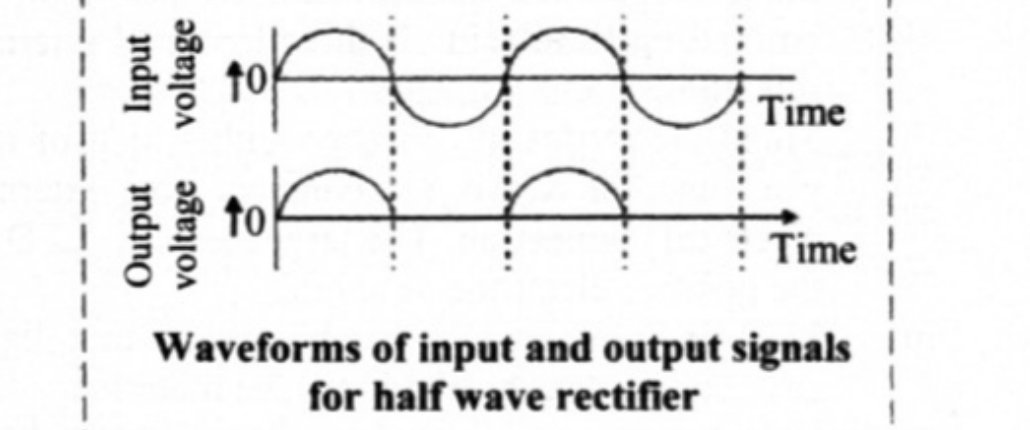
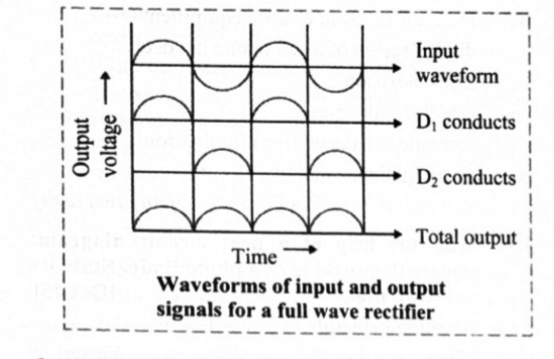
Circuit: the secondary winding of a step-down transformer (whose primary is connected to the AC mains) has one end (A) connected through a diode to a load resistor , and the other end (B) connected directly to the other end of ; the output voltage is taken across . During the positive half cycle of the input AC, end A of the secondary winding becomes positive and end B becomes negative. Thus diode becomes forward biased and conducts, so current flows (from A, through the diode and , to B) during this half cycle. During the negative half cycle of the input AC, end A becomes negative and end B becomes positive. Diode is now reverse biased and does not conduct, so no current flows in the circuit during this half cycle. Since current flows through only during the positive half cycle, and always in the same direction (A to B), the output across is a series of one-directional pulses (occurring once every full input cycle) — this pulsating, unidirectional output is the rectified (DC) output of the half-wave rectifier.
(i) V-I characteristic: for forward bias, the curve for Ge rises steeply past about 0.3 V and for Si past about 0.7 V (the current stays near zero before this and then increases very rapidly); for reverse bias, only a small, nearly constant current (of order a few A) flows over a wide range of reverse voltage, until breakdown, beyond which the current suddenly increases sharply. (ii) Threshold voltage: in forward bias, the diode current first increases only very slowly with applied voltage, until the voltage across the diode crosses a certain value — beyond this, the current increases significantly even for a very small further increase in voltage. This voltage is called the threshold (or cut-in) voltage. Breakdown voltage: a very small current flows through a p-n junction when it is reverse biased, due to minority charge carriers. If the reverse bias voltage is continuously increased, at a certain reverse voltage the current through the junction increases abruptly. This reverse voltage is known as the breakdown voltage. (iii) Since a junction diode conducts current in forward bias but does not conduct (blocks current) in reverse bias, it is used to rectify AC voltages — this one-way (unidirectional) conduction property is what makes it suitable for rectification.
A full wave rectifier consists of two diodes and connected to the two ends (A and B) of the secondary winding of a centre-tapped step-down transformer, with the load resistor connected between the (common) output point X (where both diodes' other terminals join) and the centre tap of the transformer, which is taken as the reference (ground/Y) point. During the positive half cycle of the input AC, end A of the secondary becomes positive and end B becomes negative (relative to the centre tap). So diode (connected to A) becomes forward biased and conducts, while diode (connected to B) becomes reverse biased and does not conduct — current flows through and through , from X to Y. During the negative half cycle, end A becomes negative and end B becomes positive. Now diode is reverse biased (does not conduct), while diode becomes forward biased and conducts — current flows through and through , again from X to Y. So during BOTH halves of the input cycle, current flows through in the same direction — this gives a pulsating DC output at twice the frequency of the input: the input waveform is a full sine wave (positive and negative lobes alternating), while the output waveform across consists of a series of positive-only humps, one for every half-cycle of the input (so twice as many humps as the number of input cycles).
(i) Two p-n junction diodes are connected to the two ends of a centre-tapped secondary winding, with load between the common diode output and the centre tap. During the positive half cycle of the input AC, is forward biased (conducts) and is reverse biased (does not conduct); during the negative half cycle, is forward biased (conducts) and is reverse biased. In both halves, current flows through in the SAME direction, producing a pulsating DC (unidirectional) output whose ripple frequency is double the input frequency. (ii) V-I characteristics: negligible forward current until the threshold voltage is crossed, then a steep rise; negligible, nearly voltage-independent reverse current until breakdown, then a sharp rise. Because a junction diode conducts appreciably in only ONE direction (forward) and blocks current almost entirely in the other (reverse) direction, if an alternating voltage is applied across it, current will flow only during the half-cycle for which the diode is forward biased — this asymmetric conduction is exactly what is used to rectify (convert to unidirectional) an AC voltage. (iii) Carbon, silicon and germanium all belong to the same group (they each have 4 valence electrons and the same diamond lattice structure), but their 4 bonding (valence) electrons sit at different distances from the nucleus: in carbon they occupy the second orbit (closest to the nucleus, most tightly bound), while in silicon they occupy the third orbit (farther out, less tightly bound). Because carbon's valence electrons are held much more tightly (a much larger energy is needed to free an electron for conduction), essentially no electrons become free at ordinary temperatures — carbon behaves as an insulator. In silicon, the outer valence electrons are more loosely bound (smaller energy gap), so a small but significant number of electrons can be thermally freed at room temperature — silicon behaves as an (intrinsic) semiconductor.
The two important processes are diffusion and drift. Full-wave rectifier circuit and working: two p-n junction diodes are connected to the two ends A, B of a centre-tapped secondary winding of a step-down transformer, with the load resistor connected between the common diode-output node X and the centre tap Y. During the positive half cycle of the input AC, end A becomes positive and end B negative; diode becomes forward biased (conducts) while becomes reverse biased (does not conduct) — current flows through and from X to Y. During the negative half cycle, end A becomes negative and end B positive; now is reverse biased and is forward biased (conducts) — current flows through and , again from X to Y. Since current flows through in the SAME direction during both halves of the input cycle, a pulsating DC (unidirectional) output results, at double the frequency of the input: the input waveform is a full alternating sine wave, while the output waveform across is a series of positive-only humps occurring twice as often (one per half-cycle of the input). Characteristic property suitable for rectification: since junction diodes conduct in forward bias but do not conduct in reverse bias, this is used to rectify ac voltages — the diode allows current to flow through it in only one direction, converting the bidirectional AC into unidirectional (pulsating DC) current.
Circuit: it consists of a diode connected in series with a load resistor across the secondary winding of a step-down transformer, whose primary is connected to the AC supply. The secondary's ends are labelled A and B; diode connects A to the output node X, and is connected between X and Y (Y being the other end, B, of the secondary). During the positive half cycle of the input AC, end A of the secondary winding becomes positive and end B becomes negative. Thus diode becomes forward biased and conducts the current through it — so current in the circuit flows from A to B, through the load resistor . During the negative half cycle of the input AC, end A of the secondary winding becomes negative and end B becomes positive. Thus diode becomes reverse biased and does not conduct any current — so no current flows in the circuit during this half. Since electric current through the load flows only during the positive half cycle, and in one direction only (from A to B), a unidirectional pulsating output (DC) is obtained across : the input waveform is a full sine wave, while the output waveform consists of only the positive humps of that sine wave, with a flat (zero) region during each negative half-cycle of the input — occurring at the same frequency as the input.